-
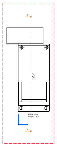
Launch the Drafting workbench by selecting the Start -> Mechanical Design -> Drafting command, and choose the option Front, Bottom and Right layout option
 from the New Drawing Creation
dialog box.
from the New Drawing Creation
dialog box.
The three views are generated.
-
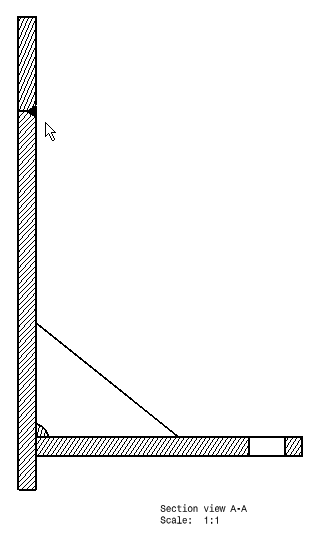
Use the offset section view icon
 to obtain this cutting profile:
-
Double-click to end the creation and position the section view.
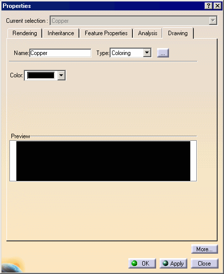
Conversely, Weld1 is hatched. To make it more visible, you must apply a material onto it and edit the properties of this material.
You have finished the scenario. Now let's take a closer look at Weld Design.