-
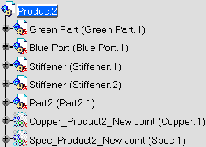
Expand the Product2 node.

Two new parts have been created and are displayed in Hide mode:
-
Copper_Product2_New Joint(Copper.1): includes the geometry of the weld shape.
-
Spec_Product2_New Joint(Spec.1): includes the geometry used to compute the weld.
-
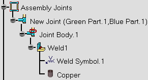
Expand the Assembly Joints node.

The Assembly Joints node is organized as follows:
-
 Assembly Joints
contains all the joints related to the parent product.
 -
 New Joint (Green Part.1, Blue Part1) indicates both parts selected
for locating the fillet weld.
 -
 Joint Body.1
gathers all joint elements.
 -
 Weld1:
indicates the weld's name.
 -
 Weld Symbol.1: indicates the annotation.
 -
 Copper: indicates the material assigned to the weld.
-
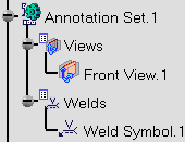
Expand the Annotation Set.1 node.

The Annotation Set.1 node is organized as follows:
-
 Annotation Set.1
contains all the annotations related to the parent product.
 -
 Views:
gathers all annotations of the product.
 -
 Front View.1: indicates the plane in which the application has
located the annotation.
 -
 Welds: gathers all annotations of the product.
 -
 Weld Symbol.1: indicates the annotation.