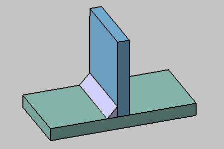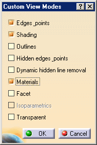
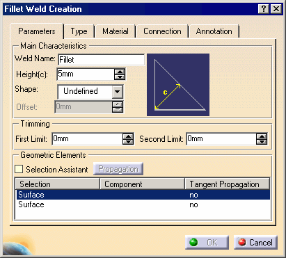
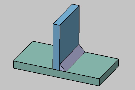
The Fillet Weld Creation dialog box is displayed:
-
Enter a meaningful name in the Weld Name field to identify your fillet weld: New Fillet
-
Uncheck Weld Symbol option.
-
Select faces as shown on the green plate and blue plate with the following order: green plate, blue plate.
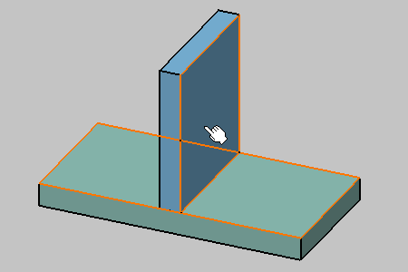
-
Click OK to create the fillet weld.
-
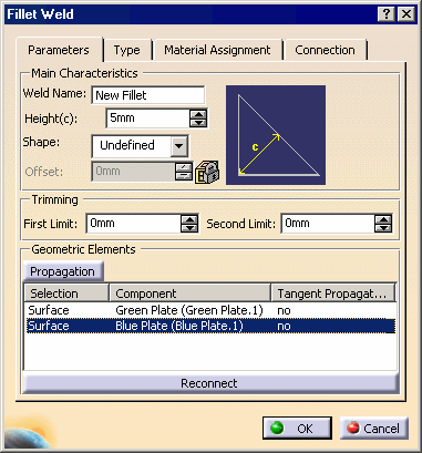
Double-click the weld in the specification tree or in the geometry area to edit it.
The Fillet Weld dialog box displays.
-
Enter new parameters if you wish to. For example, you can modify the values defining how the weld is trimmed.
-
In the Geometric Elements frame, select Blue Plate (Blue Plate.1) as the part which face is to be replaced.
-
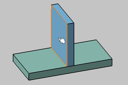
Select the opposite face of this part.
-
Click OK to confirm the operation and update the document.
The weld has been recreated on the other side of the blue part.
