|
|
This task describes how to create a Standard Opening catalog, used with the Opening command when creating an opening with a Standard opening contour. | |
|
|
The
Standard Opening catalog defines the opening contours that can be used
with the Opening command (Structure Functional Design
and Ship Structure Detail Design workbenches), or
with the Cutout command (Structure Design
workbench). The Standard Openings catalog is a standard catalog created in the Catalog Editor workbench. Standard part documents, created in the Part Design workbench, define the contours in the catalog. There are three styles of contours that may be defined:
|
|
To
create the Standard Opening catalog, you need to:
NOTE: Contours may be added to, or removed from, the catalog at a later time. |
||
General Guidelines |
||
|
The following recommendations will help you define a Standard Opening
catalog. The contour description names and parameter names should not contain any special characters or spaces. You can use underscore and dash in these names. Contour names and parameter names may be translated to the local language of the user. If your Standard Opening catalog will be used in multiple languages, you should provide NLS names for the contours and parameters. To further explain the purpose of each contour parameter, you may define a bitmap picture of the contour and its parameters. This bitmap picture is displayed in the Openings command when the contour parameters are shown. When a contour is used in your design models, the contour storage takes much less space (in memory and on disk) if it has no modifiable parameters (all parameters are set from a design table or locked in the catalog part, or the part has no parameters). You should avoid using contours with modifiable parameters whenever possible. You may include parameters in your contours that are only for descriptive purposes (information for users). If you lock these parameters, they will have very little impact on memory and disk utilization. |
||
Creating a Fixed Size Contour |
||
|
|
1. |
Create a new part named with a general description of the contour shape (e.g. Round). Use Start – Mechanical Design – Part Design from the menu bar. |
| 2. |
Create a new sketch on the xy plane, located at the origin. |
|
| 3. |
Draw the contour, using the various commands in the Sketcher. The origin of the sketch will be the contour anchor point. Exit the Sketcher and save the part. |
|
Creating a Contour with Modifiable Parameters |
||
| 1. |
Follow the steps above for creating a fixed size contour. |
|
| 2. | Define the parameters that control the size
of the contour (e.g. Radius), setting reasonable values for these
parameters. (Use the “f(x)” command, or any other way of creating
parameters.) Specify the most precise magnitude (type) for each
parameter (e.g. Length instead of Real).
These parameters display in the Openings command. If you want some parameters to be displayed and not modifiable (Locked) in the Openings command, lock the parameter value in this part (using the Lock contextual menu of the parameter). Edit the sketch (Double-click the sketch in the tree). |
|
| 3. | Define constraints for the sketch geometry
to fully control the contour shape and size. For each constraint that my vary in the final contour, define a formula referencing the part parameters (using the Edit Formula contextual menu of the constraint). Exit the Sketcher . |
|
| 4. |
Test your contour by modifying the values of the parameters in the part. Save the part. |
|
Creating a Contour with a Design Table of Sizes |
||
| 1. |
Follow the steps above for creating a parametric contour with modifiable parameters. |
|
| 2. |
Create a design table defining the value combinations for the contour parameters as follows: Create a text file (tab delimited) defining columns of the part names and parameter values. You may define this text file using Microsoft Excel and saving the result as Text (tab delimited).
|
|
| 3. |
In CATIA, open the parametric contour part (if not already open) and select the Design Table command. Select the option to create the design table from an existing file. Select OK and you are prompted to select the file with the design table values. Select the tab delimited text file that you just created and select OK. If a dialog box asks if you want to associate the columns of the table with parameters in the model, reply Yes. A window shows the parameters and values in the design table (the PartNumber column is not displayed). Select OK to store the design table. Save the part. |
|
Adding the Contours to the Catalog |
||
| 1. |
Start a new catalog with the Standard catalog type by selecting menu File – New… (catalog type) or by selecting menu Start – Infrastructure - Catalog Editor (or open your existing Standard Opening catalog to add contours to it). A catalog document with a root chapter is displayed. |
|
| 2. |
Rename the root chapter with any name you like (e.g. Standard Openings). If this catalog may contain anything other than contours, create a chapter named Contours, and create all contour descriptions anywhere under the Contours chapter. The Openings command will use only the descriptions under the Contours chapter (under this chapter and further levels of chapters and families) as contours, and any descriptions not under the Contours chapter will be ignored (when accessing the contours). If you do not create a Contours chapter (directly under the root chapter), then all descriptions in this catalog will be taken as contours. NOTE: You might create descriptions that are not contours in this catalog if you decide to combine the Standard Openings catalog with another catalog. You can create any hierarchy of chapters in this catalog in order to organize the catalog. The hierarchy of chapters will not be seen in the Openings command, but will be seen in the Structure Design Cutout command. Double-click (or Edit) the chapter under which you want to create the contour descriptions. It may be the root chapter, the Contours chapter or a lower level chapter. |
|
To define descriptions for a contour with a design table |
||
| If this catalog will not be stored in ENOVIA, then the single parametric part with a design table is most efficient. | ||
|
If this catalog may be stored in ENOVIA, now or in the future, you should create the catalog with resolved parts (one part for each design table row), which have the design table already applied to the parameters and removed from the parts. A part with an active design table cannot be entirely stored in ENOVIA. To cause the resolved parts to be generated in the correct directory, set the following while you work on the catalog, and reset it when this catalog is completed. |
||
| Select Tools – Options - Infrastructure – Catalog Editor – Catalog page. | ||
| Set the Resolved Family Components – Folder to the directory of your Standard Openings catalog, and select OK. | ||
| 1. |
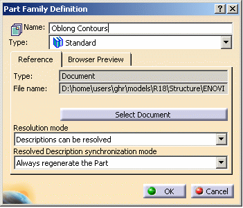
Select the Insert – Add Part Family menu. The Part Family Definition dialog box displays. Define any name for this family. The chapter name is not shown in the Openings command, but is shown in the Cutout command. |
|
| 2. |
Click the Select Document button. Select the part for this contour, and select the Open button. |
|
| 3. |
If this catalog will not be stored in ENOVIA, specify the Resolution Mode as Descriptions can be resolved. If the catalog may be stored in ENOVIA, specify the Resolution Mode as Descriptions will be resolved. |
|
| 4. | Specify the Resolved Description synchronization mode as Always regenerate the Part. | |
|
Select OK to create the part family,
including descriptions for each design table entry.
If you specified the Resolution Mode as Descriptions will be resolved, the resolved parts will be created in the directory for this catalog (as specified in Tools – Options). |
||
To define descriptions for a parametric or fixed size contour |
||
| You may add the new description into a new family, or an existing simple family (not a part family). | ||
| 1. |
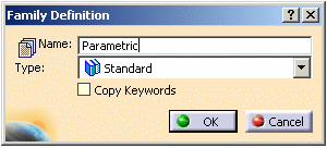
To create a new family, select the Insert – Add Family menu. The Family Definition dialog box displays.
|
|
|
Define any name for this family (it is not shown in the Openings command, but is shown in the Cutout command). Select OK to create the family. |
||
| 2. |
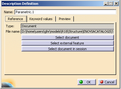
Edit the family for the new description. Select the Insert – Add Component menu. The Description Definition dialog box displays.
|
|
| 3. |
Select the Select Document button. Select the document for this contour, and select the Open button. Select OK to create the description within this Family. |
|
Set the Project Resource Management Resource Name |
||
| The Standard Opening catalog is specified in the StructureOpeningsCatalog resource of your Project Resource Management XML file. | ||
| 1. | Set this resource information. Using any text editor, edit the Project Resource Management project file (XML) for the project that will use this new Standard Opening catalog. The sample project file is in …\intel_a\ startup\EquipmentAndSystems\ProjectData\ Project.xml NOTE: For UNIX, replace intel_a with your operating system designation. |
|
| 2. | Find all occurrences of the StructureOpeningsCatalog resource.<Resource Name="StructureOpeningsCatalog" … There is usually only one under the Structure discipline. |
|
| 3. | If the catalog will not be in ENOVIA, set the
Driver=File and
Location= your catalog path name.
If the catalog is in ENOVIA, set the Driver=EnoviaV5 and Location= your catalog name in ENOVIA. |
|
Create a Bitmap for Each Contour |
||
|
Bitmap files provide a graphic description of
the shape and parameters of each contour. A bitmap file may be
created for each contour description in the catalog. The bitmap file
for each contour is optional, but recommended. The bitmap files for contours are defined in the directory described by the Project Resource Management resource StructureDetailingFeatureBitmapPath. The default bitmap directory is: …\intel_a\startup\EquipmentAndSystems\Structure\DetailingFeatures\Bitmaps In the bitmap directory, the contour bitmap file name is XXX.bmp, where XXX is the contour description name (without NLS translation). For contours, the bitmap files should have Width=133 pixels, Height=170 pixels and Colors=”True Color” (24 bit) at 72 dpi. You can get these attributes by copying an existing Contour bitmap file (e.g. Sfm_Round.bmp) and editing the picture. Each bitmap file should show the contour shape (roughly) and describe all parameters of the contour. You may save work by copying the same bitmap image for multiple contours, since the image is only a graphic aid to help the user understand the contour parameters. |
||
Defining the NLS Names for the Contours and Parameters |
||
|
The contour description names and parameter names defined in the catalog may be translated to the language of the user using an NLS file. |
||
| 1. | To define NLS translations for contour and
parameter names: In any text editor, open the file: …\intel_a\resources\msgcatalog\CATSfmStdOpeningObjects.CATNls (You may want to keep a copy of the original file as a backup.) |
|
| 2. | For each contour description name XXX with
NLS name=YYY, specify the line:CATSfmStdOpeningObjects.ContourName.XXX = “YYY”; |
|
| 3. | For each contour parameter name AAA with NLS
name=BBB, specify the line:CATSfmStdOpeningObjects.ParameterName.AAA = “BBB”; |
|
| 4. | When all contour and parameter NLS names are specified, save the file in its original location. | |
|
|
||


