 |
This task explains how
to create a specifications catalog. |
 |
1. |
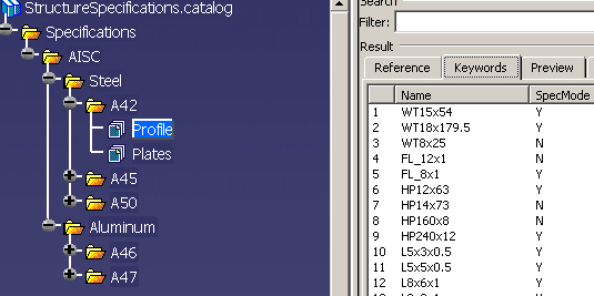
Click Start - Infrastructure
- Catalog Editor to start the Catalog Editor. The image below is of
the sample catalog included with this application. You should follow this
structure if you intend to make a new catalog.
 |
|
2. |
Rename Chapter.1 to
Specifications  (or
any other name). To do this, right click on it, select Chapter.1
object - Definition in the menus and enter Specifications in the
Chapter Definition dialog box. (or
any other name). To do this, right click on it, select Chapter.1
object - Definition in the menus and enter Specifications in the
Chapter Definition dialog box. |
|
3. |
You need to create the keyword
SpecMode and assign it two discrete values - Y and N. These
values will be used to include or exclude a section or thickness value from
the preferred list. If you select N, then the part is not included in your
preferred list. Y means it will display in the preferred list. To create
the keyword, select Specifications and click the Add
Keyword button  to
display the Keyword Definition dialog box. to
display the Keyword Definition dialog box.
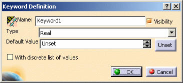
- Enter SpecMode in the name field. Check Visibility
if it is unchecked.
- Select String in the Type field
- Change the Default Value entry to Y or N - whichever you
prefer
- Check With Discrete List of Values
- Click OK.
|
|
4. |
The Legal Value Definition
dialog box displays.
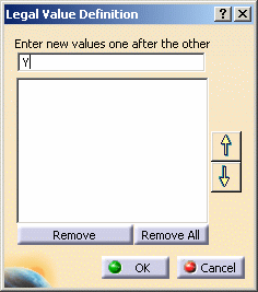
Enter Y in the first field and press Enter. Enter N and press Enter.
Click OK to close the box. Both values will display in the lower field. |
| |
5. |
To create a standard, make
Specifications active and click the Add Chapter button
 . In the Chapter
Definition dialog box that displays enter the standard name (in this
example it is AISC) and make sure the Copy Keywords check box is
checked. Click OK and the standard displays in the
specifications tree. . In the Chapter
Definition dialog box that displays enter the standard name (in this
example it is AISC) and make sure the Copy Keywords check box is
checked. Click OK and the standard displays in the
specifications tree. |
|
6. |
Make the standard active and
create a materials entry by following the same procedure. It can be any
material, in this example it is Steel. The entry is added to the
specifications tree. |
|
7. |
Make the material entry active and
create a grade entry by following the same procedure. In this example it is
A42. |
 |
The material-grade
combinations in the Specifications catalog should match the
material-grade combinations defined in the Material catalog. If they are
not matched, you will get an error message when creating a shape or
plate in Structure Design, and a warning when creating a stiffener or
plate in Structure Functional Design and Structure Detail Design. |
|
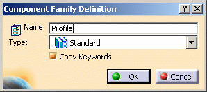
8. |
Double click A42 and
click the Add Family button. In the Component Family
Definition dialog box enter Profile in the Name
field. Create a second entry at the same level, naming it Plates.
Leave the Type entry at Standard, and check Copy Keywords.
 |
|
9. |
You need to link the two entries
Profile and Plates to corresponding documents. Select
Profile and click the Add Component
 button to display the
Description Definition dialog box. button to display the
Description Definition dialog box.
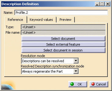
Click Select Document and navigate to the directory where
yours parts (resolved sections) are. Select one and click Open to return to
the Description Definition dialog box. You can modify the
default SpecMode value: to do this, select the Keyword Values tab in the
Description Definition dialog box. If the SpecMode value is not
what you want, or if no value is displayed, then select SpecMode and select
the value you want in the Value field. Click OK when you are
done. Repeat the process for all parts you want to add.
Select Plates, click the Add Part Family Components button,
click Select Document and navigate to the directory where the CATPart
containing your thickness design table is stored and select that. The
default CATPart sent out with the sample catalog is named Thickness.CATPart. |
|
 |