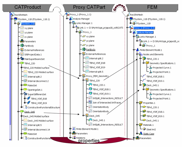
Workflow

From Design Model to FEM
For instance, at this stage, the Proxy CATPart along with the FEM is self-sufficient for assembly analysis purposes without relying on the original Design Model.
Formulas and Equivalent Dimensions
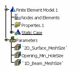
The three parameters below are provided in order to facilitate the multi-edition for all the mesh parts.
-
2D_Surface_MeshSize controls the size for all the Surface mesh parts.
-
Opening_Min_HoleSize controls the minimum hole size for all the Surface mesh parts.
-
1D_Beam_MeshSize controls the size for all the Beam mesh parts.
- 2D_Surface_MeshSize
- Opening_Min_HoleSize
- Mesh_Capture_Tolerance
- Constraint_Tolerance_Value
- 1D_Beam_MeshSize

Mesh Quality Improvement
For instance, for a complex shell, adjusting the constraint sag manually could reduce the number of internal edges to be considered as the mesh constraint. By default, the constraint sag is set to 0.0. This implies that the surface will be constrained with all of its internal edges, if any.
For more information on how to improve the mesh parts quality you may refer to Advanced Meshing Tools User Guide, Surface Mesher in Analysis.