 |
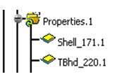
Mesh parts, properties, and materials are retrieved through the design
model, and are found under Properties set. |
|
|
 |
|
|
2D Property - Plate
|
|
|
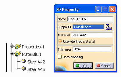
A 2D property entity manages material and
grade as well as thickness attributes.
Only one user-defined material is created per combination of material
and grade. |
|
|
 |
|
|
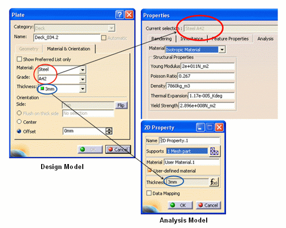
In the dialog boxes below, you can see how
the 2D properties are retrieved from the design model and applied to the
analysis model. |
|
|
 |
|
|
1D Property - Beam and Pillars, Stiffener, Stiffener on Free Edge
|
|
|
A 1D property carries information for 1D mesh such as material,
orientation, and section parameters. (The section parameters are
retrieved form the section catalog.)
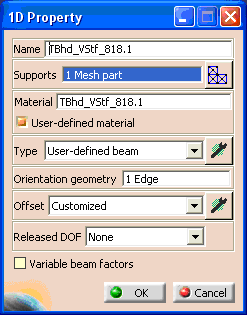
Any section coming from the design model is mapped to the
User-defined beam type.
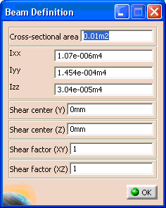
Click the button beside the Type field, and the Beam Definition dialog box displays.
 |
|
|
About Section Parameters
|
 |
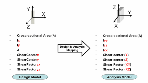
The Axis definition in the design model is different from the one used
in the analysis model. The mapping described below is used to place the
values of the parameters stored in the section document on to the Beam Definition parameters. |
|
|
For more information on Structure Function design section parameters,
see Section Parameters Explained.
For more information on Analysis section parameters, see the Generative Structural Analysis
User Guide. |
|
|
Obtaining the Section Parameters
|
|
|
To obtain the section parameters while preparing the section catalog,
you can use the Standard Steel tables. (Note that the principal moment of inertia
is sometimes referred to as Iu/Iv.) |
|
|
You can also use the Generative Structural Analysis
workbench to obtain the section parameters expressed in the principal
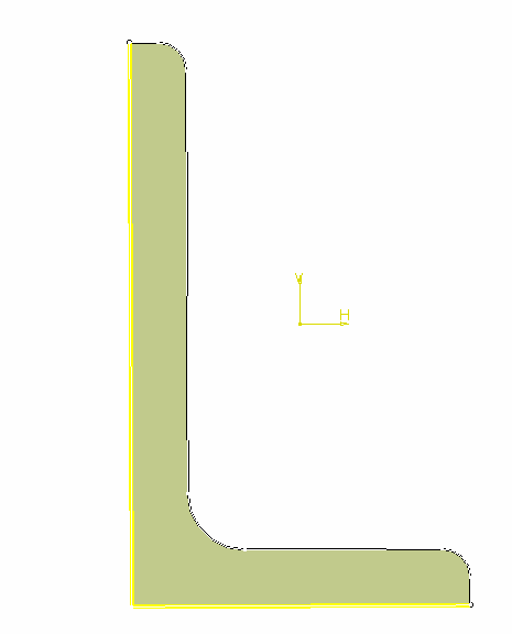
axis of the beam. (The axis where the matrix is diagonal.) 1. In the
Generative Shape Design workbench, create a face from the sketch of a
section.
 |
|
|
2. Go to the Generative Structural Analysis
workbench, and click the
1D Property button
 . .
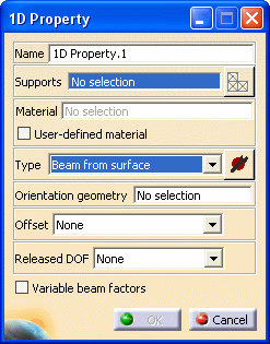
The
1D Property dialog box displays.
|
|
|
3. Select Beam from Surface
from the Type drop down list, and click the Component
Edition button
 . .
The
Beam Definition dialog box displays.
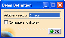
|
|
|
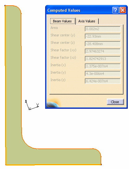
4. Select the Compute and display checkbox to compute and
display the required section parameters for a given surface.
Click OK and the Computed Values dialog box
displays. |
|
|
 |
|
|
Refer to these
computed values to obtain the section parameters. |
|
|
Orientation Geometry - Beam and Pillars, Stiffener, Stiffener on Free
Edge
|
|
|
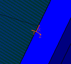
To orient a 1D section properly, the local xyz vector is defined so that
the x-axis goes along the trace of the profile, while the y-axis is the
major component of the principal moment of inertia axis, and z-axis is computed accordingly.
|
|
|
Offset - Beam and Pillars, Stiffener, Stiffener on Free Edge
|
|
|
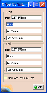
The Anchor point (including the U and V
offsets) used in the design model is taken into account to valuate the
fields on the Offset Definition dialog box.
Click the button beside the Offset field on the
1D Property dialog box, and the Offset
Definition dialog box displays.
|
|
|
|


![]() .
.
![]() .
.


