This task explains how to synchronize the plane systems of an existing SFD system after a modifying definitions in the ProjectReferencePlanes XML file. (Refer to Project Reference Planes to learn how to define the planes.)
NOTE: The format for the ReferencePlanesSystem.xml file has changed. It now incorporates additional attributes such as color and short names. Detailed instructions for converting the file from R16 to R17 are given at the top of the XML file.
- Change the name(s) of one or more planes.
- Change the offset value(s) of one or more planes.
- Add new planes in an existing plane system.
It is recommended to do one type of change at a time. (Change the names, or change the offset values, or add new planes).
Deletion of planes is not supported.
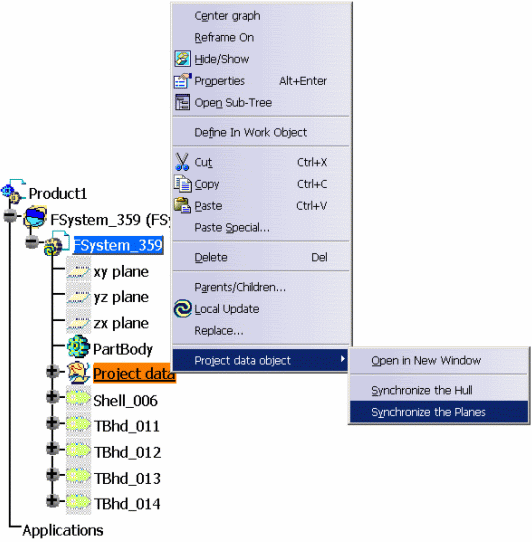
The command is available through a contextual menu on the Project data.
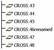
- Rename CROSS.46 plane into CROSS.46renamed.
- Modify offset values for CROSS plane system by adding 10 meters to each plane starting at CROSS.47
- Add new planes to CROSS plane system.
Open and replace CROSS.46 by CROSS.46renamed as shown below.
(Changes are highlighted.)
Original XML file:
<Plane Name =CROSS.46 TYPE=PRIMARY OFFSET = 46000 />
<Plane Name =CROSS.47 TYPE=PRIMARY OFFSET = 47000 />
Modified XML file:
<Plane Name =CROSS.46renamed TYPE=PRIMARY OFFSET = 46000 />
<Plane Name =CROSS.47 TYPE=PRIMARY OFFSET = 57000 />
Before starting CATIA, set the PRM resource ProjectReferencePlanes
such that it points to the modified xml file.
NOTE: To access the contextual menu, the Structure Functional Object Design workbench or Structural Detail Object Design workbench must be active.


Open ReferencePlanesSystem.xml and add 10 meters to the offset value of each CROSS plane from CROSS.46 to last CROSS plane.
Original:
<Plane Name =CROSS.46 TYPE=PRIMARY OFFSET = 46000 />
<Plane Name =CROSS.47 TYPE=PRIMARY OFFSET = 47000 />
<Plane Name =CROSS.48 TYPE=PRIMARY OFFSET = 48000 />
<Plane Name =CROSS.49 TYPE=PRIMARY OFFSET = 49000 />
<Plane Name =CROSS.197 TYPE=PRIMARY OFFSET = 197000 />
<Plane Name =CROSS.198 TYPE=PRIMARY OFFSET = 198000 />
<Plane Name =CROSS.199 TYPE=PRIMARY OFFSET = 199000 />
Modified:
<Plane Name =CROSS.46 TYPE=PRIMARY OFFSET = 46000 />
<Plane Name =CROSS.47 TYPE=PRIMARY OFFSET = 57000 />
<Plane Name =CROSS.48 TYPE=PRIMARY OFFSET = 58000 />
<Plane Name =CROSS.49 TYPE=PRIMARY OFFSET = 59000 />
<Plane Name =CROSS.197 TYPE=PRIMARY OFFSET = 207000 />
<Plane Name =CROSS.198 TYPE=PRIMARY OFFSET = 208000 />
<Plane Name =CROSS.199 TYPE=PRIMARY OFFSET = 209000 />
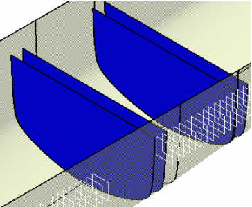
The picture below shows a SFD system containing four transverse bulkheads created on planes CROSS.44, CROSS.46, CROSS.48 and CROSS.50 before Synchronize the Planes.

The picture below shows the same SFD system after Synchronize the Planes. An update on the SFD system was necessary to recomputed all the objects impacted by this change.

You can notice now that the two transverse bulkheads created on CROSS.48 and CROSS.50 have moved 10 meters in fore direction and there is a 10 meters gab between CROSS.46 and CROSS.47.
To do so, modify the current ReferencePlanesSystem.xml as shown below:
Current:
<Plane Name =CROSS.46 TYPE=PRIMARY OFFSET = 46000 />
<Plane Name =CROSS.47 TYPE=PRIMARY OFFSET = 57000 />
Modified:
<Plane Name =CROSS.46 TYPE=PRIMARY OFFSET = 46000 />
<Plane Name =NewPlane.1 TYPE=PRIMARY OFFSET = 48000 />
<Plane Name =NewPlane.2 TYPE=PRIMARY OFFSET = 49000 />
<Plane Name =NewPlane.3 TYPE=PRIMARY OFFSET = 50000 />
<Plane Name =NewPlane.4 TYPE=PRIMARY OFFSET = 51000 />
<Plane Name =NewPlane.5 TYPE=PRIMARY OFFSET = 52000 />
<Plane Name =NewPlane.6 TYPE=PRIMARY OFFSET = 53000 />
<Plane Name =NewPlane.7 TYPE=PRIMARY OFFSET = 54000 />
<Plane Name =NewPlane.8 TYPE=PRIMARY OFFSET = 55000 />
<Plane Name =NewPlane.9 TYPE=PRIMARY OFFSET = 56000 />
<Plane Name =CROSS.47 TYPE=PRIMARY OFFSET = 57000 />
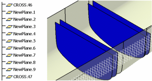
The pictures below show your SFD system after Synchronize the Planes.
