Adjust Layout by Shifting Parts
|
|
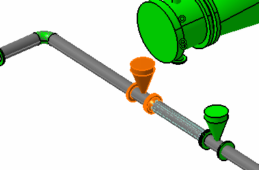
This task shows you how to shift parts in your design document. See also Adjust Layout by Changing Angle. Piping parts/equipment have been used as examples below. The process is the same for other part types. | |
|
|
You can shift parts
in a design by selecting a connector, entering a value to adjust a run
and entering a value to adjust a pipe. All three options are explained
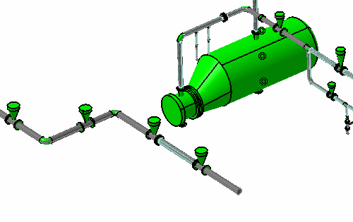
below using this design.
|
|
|
|
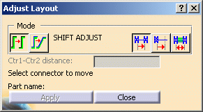
1. | Click the Adjust Layout button
|
| 2. |
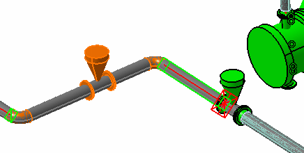
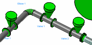
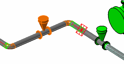
Click the Move Connector to Connector button and select a connector on the part you want to move - the part will move in the direction of the connector vector. (The connector you select must be free - it must not be connected to another part.) In the scenario below the user wants to move the elbow. Red markings display to show the location to which the elbow will move and the run that will be adjusted.
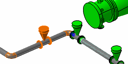
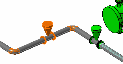
Click Apply to complete the operation. The elbow, as well as the run it is on and the parts on that run, shift to the new location. (See note below.) If the Auto Parts option is enabled then automatic parts will also be placed, as required by the design rule.
NOTE: The run moved in the image above because the elbow you want to move (Elbow 1) is connected to it. If a part is not connected to a run then the run will not move. In the image below, if you move Valve 1 to Valve 2, then Run 1 will not move, because Valve 1 is not connected to it.
|
|
| 3. |
Click Apply to complete the operation. The elbow, as well as the run it is on and the parts on that run, shift to the new location.
|
|
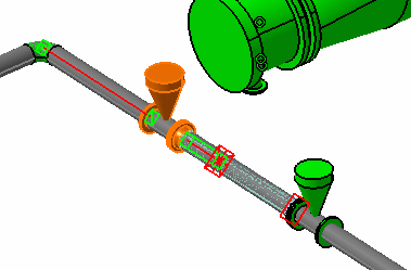
| 4. |
Click Apply to complete the operation.
|
|
|
|
CONDITIONS Some conditions that further explain the function are listed below: |
|
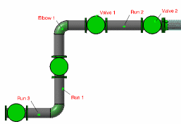 In the example above, Elbow 1 is connected to Run 1. If you move Elbow 1 along Run 2, then the application searches until it finds the first parallel run, and stretches it. Run 3 above is parallel to Run 2, and it will stretch so that Run 1 can move. If there is no parallel run then the following conditions apply. |
||
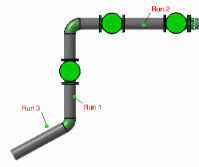 If there is an angled run with a free end, such as Run 3 above, then the entire run will move along with Run 1 (it will not stretch). The run will also move if there is a part, such as a valve, at the end of Run 3. |
||
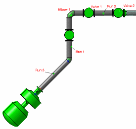 If there is equipment at the end of Run 3, then the run will not move or stretch. In this case the shifting operation will not be performed. |
||
|
|
||
