|
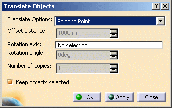
The Translate function is available when you
have checked the option Allow translate and rotate copied objects
in the Copy-Paste 3D Systems
dialog box. The Translate Objects dialog box displays
when you click OK in the Copy-Paste 3D Systems dialog box.
Although it allows you to position copied objects, you can also use it
to position existing elements in your design. See
Using the Copy/Paste
Function to learn more about the copy function. The Translate
Objects
dialog box allows you five possibilities for positioning objects. They
are explained as separate tasks in this section. |
 |
1. |
Select the Point to Point
option in the Translate Options field.

The Point to Point option allows you to position your element
by defining the direction and distance using points. You can place the
points on any surface and the distance will be calculated
using the distance between two points. The direction will be calculated
by using the vector between the two points. |
|
|
2. |
Define the two points by clicking on a surface.
When you click on a surface the points will be placed in its center. if
it is a circle or square element the point will be in the center. If you
click a part, such as a pipe, the point will be placed between the two
ends. You cannot place the point in any location but the center of the
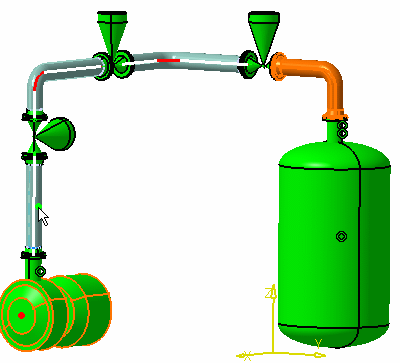
object. In the image below the first point has been placed on the
compressor (the red dot) and the second is being placed on the pipe.
 |
|
3. |
The Offset Distance field is not relevant for this option. |
|
4. |
To rotate the element you just positioned,
select the
Rotation Axis
field in the Translate Objects dialog box and define an axis.
Usually you can select a line, such as a connector, segment or
centerline to define the axis. Three things happen after you select a
line: a dashed line shows you the axis, the
Rotation Axis field reads "rotation axis defined";
and the Rotation Angle field becomes available.
Enter a positive or negative value in the Rotation Angle
field, or use the Up/Down arrows to select a value, and press Enter.
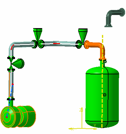
The positioned object will rotate accordingly. In the image in Step 5, the
dashed yellow line is the rotation axis. The element has been
rotated. |
|
5. |
The Number of Copies field shows the
number of copies you had selected in the Copy-Paste 3D Systems
dialog box. It is shown for informational purposes - you cannot make
changes to it in this dialog box. |
|
6. |
Click OK to accept your changes,
Apply to continue working.

Click Close if you want to exit
without saving the changes. If you had clicked Apply in the
Copy-Paste 3D Systems
dialog box then you will be taken back to it. If you had clicked OK,
you will exit the command.
If the option Keep objects selected was checked, then the element you pasted will
remain selected in the specifications tree after you exit the command. |


