 |
This task explains how to activate
a plane system grid.
You use the
Activate Grids command
to view a grid in your 3-D document. Viewing the grid enables you to
define an offset plane on a grid line. You can then define offset
distances to place equipment, or to route a run using the EdgeLine
mode. |
 |
To
use this command, you need to have in your 3-D document a CATPart with
plane system grids defined in it (created either in the Structure Detail Design or Structure
Functional Design applications). See Creating a Plane
System Grid in the Structure
Detail Design and Structure Functional Design User Guides. |
 |
1. |
In your 3-D document,
click the
Activate Grids button
 . .
The Plane Grids dialog box
displays. |
|
2. |
Select a plate in your 3-D document,
or Working Supports from the specifications tree,
and a
list of plane system grids that you can activate displays in the Plane Grids
dialog box.
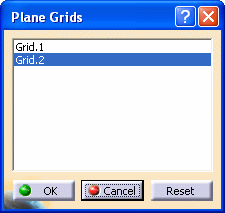
Select the plane system grid from the list, and the selected grid
displays in your 3-D document.
After selecting a plane system grid that you want to activate, click OK.
The selected plane system grid is now active.
- NOTE: Each time you enter another workbench, you need to
reactivate the grid by repeating these steps.
|
 |
You can use the plane
system grid to define offset distances when placing equipment, and to
route a run parallel to the grid line, using the EdgeLine mode. |
|
|
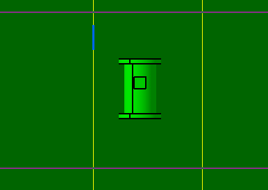
The examples below show how to place equipment using the plane system
grid:
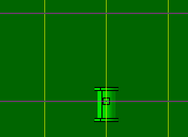
- Select a point at the intersection of the grid lines, and
place a part at this point.

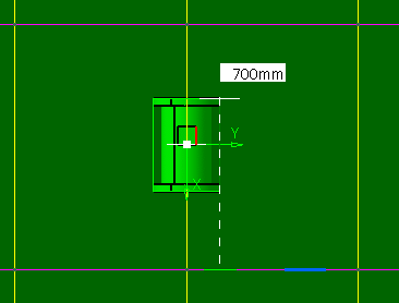
- Place an offset plane on a grid line (using the Advance Offset Plane
command) and move the equipment the indicated distance.
- Place another offset plane on a grid line and move the
equipment the indicated distance.
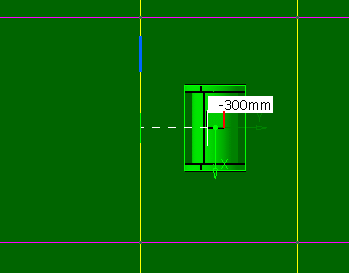
- The equipment is placed at the desired location.
|
|
|
The examples below show how to create a run using a plane
system grid:
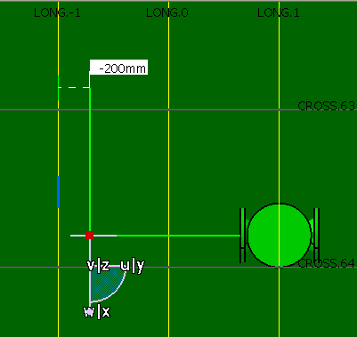
- Place an offset plane on a grid line using the Advance Offset Plane
command.
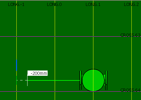
- Using the EdgeLine mode, route a run parallel to the grid
line.
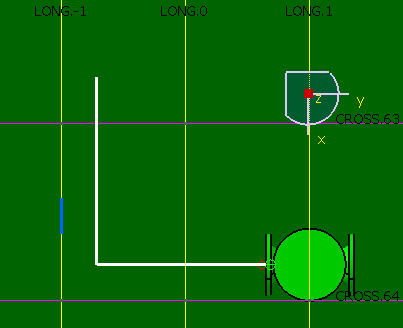
- The route is created. In this example, one of the segments is parallel to the LONG -1
grid line.
|
|
3. |
You can deactivate a grid.
Click the Reset button to deactivate the plane system grid
from the document.
|
![]()