Generating a Drawing
|
|
This task shows you how to generate a 2-D drawing from a 3-D document. | |
|
|
Piping parts are used in this
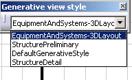
task. The procedure is the same for all types of parts. Before you can use this process, you need to set Options as follows: From the menu bar, select Tools - Options - Mechanical Design - Drafting. Select the Administration tab and uncheck the option Generative View Style. |
|
| If you want your dimensions on
the 2-D representation of the heavy bendables to be associative with the
3-D heavy bendable, create Polyline type heavy bendables using the PRM
setting BendablePolyline. To enable the Polyline option, enter
the value 1 in the Location field.
For more information, see List of PRM Resources and Flags. |
||
|
|
1. | Open the 3-D document from which you want to generate a drawing. |
| 2. | From the menu bar, click
Start - Mechanical Design - Drafting.
Either of two dialog boxes display, depending on the type of parts used in your 3-D document.
A new drawing window opens. |
|
| 3. | Click Window - Tile Vertically to view both the 2-D and 3-D documents. | |
| 4. | Click the Front View
button |
|
|
|
Front View is used for the sample images in this task. Select a view command that allows you to best manipulate and view your document. | |
 The Generative View Style dialog box displays. If it is not already selected, select the XML file that contains the settings you want to use to generate your drawing.
|
||
| 5. | You can select one or more objects
in the document, and the generated drawing will include only these
objects.
If you do not select an object, the entire document will be used to generate the drawing. |
|
|
|
Before you define a plane, you
can point to a part in the 3-D document and see a preview of the 2-D
orientation in the Oriented Preview box. If you have a run displayed in your document, it may interfere with the following steps. You can display a run as Line/Curve section, or hide it to more conveniently complete these steps. |
|
| 6. | Define a plane by clicking the
flat face of a part, or by selecting a plane from the specifications tree.
A full preview displays in your 2-D drawing.
You can use the manipulator |
|
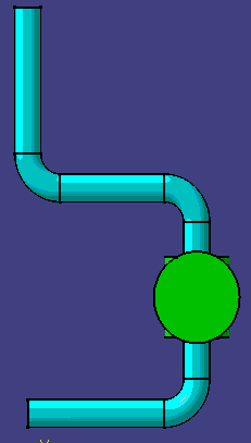
| 7. | Click anywhere in the 2-D document
to generate the 2-D image. The image below was made after specifying the
Single graphic representation in the XML file.
|
|
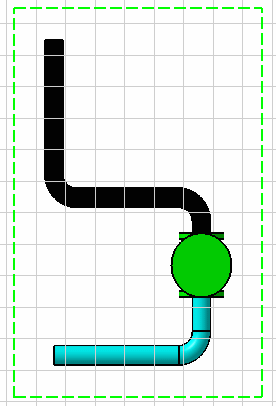
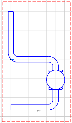
| The following image shows a Double
graphic representation (as specified in the XML file).
|
||
| 8. | You can update your 3-D document
and view the changes in the 2-D image. After updating your 3-D document,
click the Update Current Sheet button
You see the changes reflected in the 2-D drawing. |
|
| When updating a spool or a group
type object, the Update Current Sheet button is unavailable.
You cannot view changes in the 2-D image.
To view changes in the 2-D image, do the following: |
||
| After updating the spool,
right-click on the spool in the specifications tree.
Select Hide/Show from the drop-down menu. Make the 2-D window active, and the Update Current Sheet button is available. Click the Update Current Sheet button in the 2-D image. You see the change reflected in the 2-D drawing. |
||
|
|
You can get more information on manipulating 2-D drawings in Drafting documentation. | |
 to change the view.
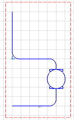
![]()