- Multi-selection of input elements is available.
- Elements can be selected in the specification tree or in the 3D viewer.
- In a Part context, you can select:
- a Geometrical Set: all visible surfaces are selected.
- an Ordered Geometrical Set: all visible surfaces are selected.
- a Body or a Partbody: the solid associated is selected, if it is visible.
- a hybrid body: all visible surfaces are selected, as well as the associated solid, if it is visible.
- the part itself, according to the rules above.
- In a Product context, you can select the product, according
to the rules above. Note that:
- transformations may be applied to create the mesh in the coordinate system of the active part,
- Surface Tessellation is not compatible with the cache system,
- Surface Tessellation applies only to loaded referenced documents.
- You can specify the maximum size of the triangles and the maximum distance (sag) between the geometry and the triangles.
- You can choose to create Distinct or Grouped tessellations.
- Note that selecting an element and selecting the components of
the element lead to different results. For example,
- if you select a join made of 5 surfaces, you will create one mono-cell tessellation, with both the Distinct and the Grouped option.
- If you select the 5 surfaces of the join, you will create 5 tessellations with the Distinct option, and one 5-cell tessellation with the Grouped option.
- The free edges of the tessellation are those of the surfaces or solids.
- To avoid free edges between the tessellations of several contiguous
faces,
you can join them with the Join action of Quick Surface Reconstruction or Generative Shape Design.
They will then be processed as a single surface.
For a better understanding, we show you the output tessellations in Triangles mode.
-
Click Tessellation
 .
The Tessellation dialog box is displayed.
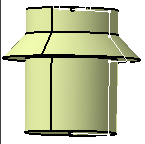
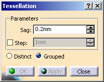
-
Select the surfaces. Click Apply.
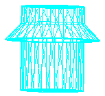
-
You can modify the Sag value,
that is the maximum distance between the geometry and the triangles:
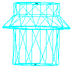
it has been increased to 1
-
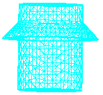
You can also select the Step check box to control the length of triangles:
-
Select an output option:
-
Distinct will create separate tessellations, i.e. one tessellation for each input element. The names of the tessellations contain the names of the input elements.
-
Grouped will create one multi-cell tessellation, named Tesselation.x. The number of cells corresponds to the number of input elements.
-
-
Click OK to validate and exit the dialog box.
![]()