 |
This task shows you how to place
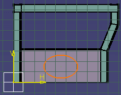
cutouts in the two plates just created. You will first sketch the cutout
contour. You can do so in a new geometrical set of the Part containing
construction geometry. |
 |
1. |
Activate the Part
containing the construction geometry to switch to the Wireframe and Surface
Design workbench, and insert a new geometrical set (Insert ->
Geometrical set). |
 |
|
Don't forget to work
without links when creating construction geometry. |
| |
2. |
Click the Sketcher icon, then
select the plane in which you want to sketch the contour. The Sketcher
workbench opens. |
 |
|
3. |
Using Sketcher tools, sketch the
contour. |
| |
4. |
Double-click the
root product to return to the Structure Design workbench. |
| |
5. |
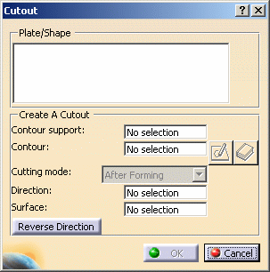
Click the Cutout
 icon.
icon.The Cutout dialog box opens. |
 |
| |
6. |
Select the two plates in which
you want to place cutouts. |
| |
7. |
Click the Contour
field and select the contour you sketched, then a grid line in the Y
direction to define the angle of the cutout. Note: When you make a
multi-selection of plates, the After Forming cutting mode only is
available. |
| |
8. |
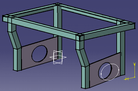
Click OK
in the Cutout dialog box to place the cutout. Cutouts are visible in the
geometry area. |
| |
|
 |
|
 |


![]()