In this operation you will specify the geometry, the tool path style and the tool characteristics.
-
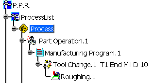
Click Roughing
 .
.
A Roughing.1 entity and a default tool are added to the program.
The Roughing dialog box is displayed.
The status light on the Geometric components tab is red ( )
which means that you must select
the part geometry in order to create the operation.
-
Click the red area that represents the part.
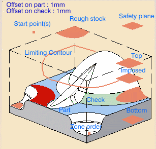
The dialog box shrinks to allow you to select the part in the viewer. -
In the viewer, click the part.
Double-click anywhere in the viewer to confirm your selection and to redisplay the dialog box.
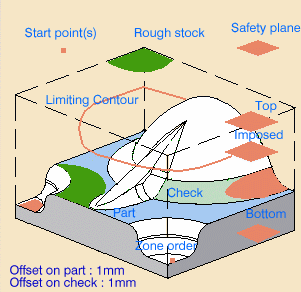
The red area in the geometric area is now green to indicate that the geometry has been selected. -
Click the sensitive area that represents the rough stock.
The dialog box shrinks to allow you to select the rough stock in the viewer. -
In the viewer, click the geometry that defines the rough stock.
The red area in the geometric components tab is now green to indicate that the geometry has been selected.
-
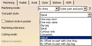
Go to the Machining strategy tab (
 )
and select Helical as Tool path style.
-
Go to the Tool tab (
 )
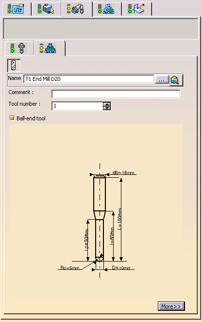
and change the Name of the tool to T1 End Mill D20.
Then click More.
-
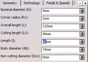
Change:
- Nominal diameter (D) to 20mm
- Corner radius (Rc) to 2 mm
- Overall length (L) to 120 mm
- Cutting length (Lc) to 90 mm
-
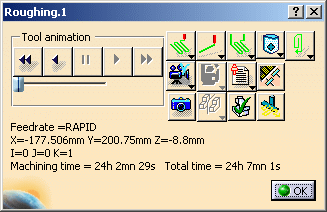
Click Tool Path Replay
 .
.
The tool path is displayed and the display and analysis dialog box is called up.
-
Click OK. The tool path is erased from the viewer and you come back to the operation dialog box.
-
Click OK to close the dialog box.
Now we are going to use ZLevel machining on the walls of the pocket and the outside of the part.
![]()