First you define the machining areas and then you assign an operation to each of them.
This is a useful approach if, before you start machining, you are aware that the part has areas
that will require different types of operation.
A machining area can be:
- the whole part (for example, in roughing),
- a subset of the faces on the part,
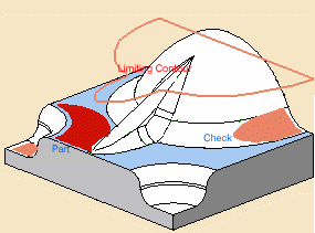
- a subset of faces on the part with a limiting contour.
Another feature of machining areas is their ability to be divided into
horizontal,
vertical and sloping areas and have operations assigned to these areas.
-
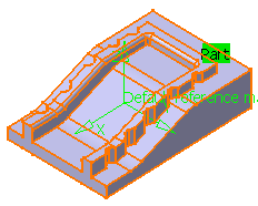
Open file DemoRasa.CATPart in the samples directory.
-
Click Machining/Slope Area
 .
.
-
Click the red area in the sensitive icon and select the whole part in the viewer.
Double-click to confirm your selection and redisplay the dialog box.
Change the Name to MyMachiningArea.
-
Select the Slope Area check box.

This activates the Define and Operations tabs.
-
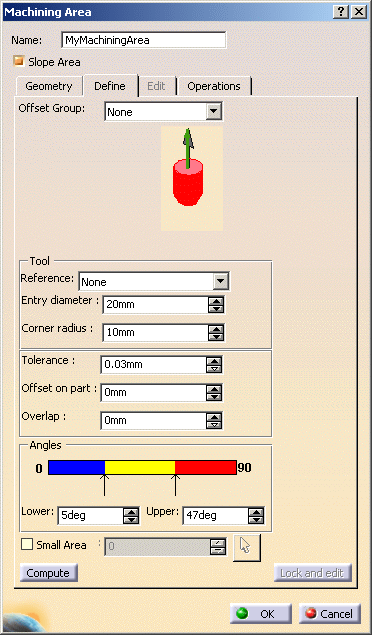
Go to the Define tab to define a tool to use,
the machining tolerance and the offset to use on the machining area. -
Use the default angles settings.
-
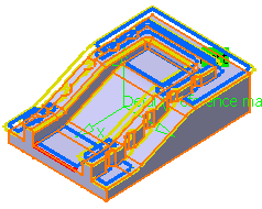
Click Compute. The three different types of area are displayed on the part
(Vertical, Intermediate, Horizontal) and are now listed in the Define tab of the dialog box.
By default, they are all displayed.
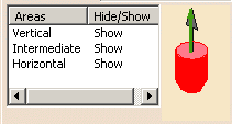

- You can hide or display an area using its contextual menu
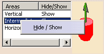
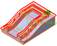
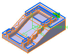
- Please note that Horizontal and Intermediate
areas are defined as being inside the lines,
whereas Vertical areas are defined as being outside the
lines, e.g.:
- Only Vertical areas are shown, they are the areas not
inside the closed red contours:
- Only Horizontal areas are shown, they are the areas
inside the blue closed contours:
- Only Vertical areas are shown, they are the areas not
inside the closed red contours:
- The Full display of area
 check box provides a fuller display that enables you to see
overlapping areas.
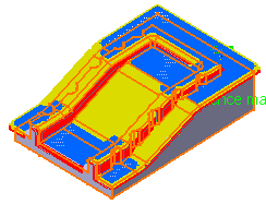

- The vertical area corresponding to the outside of the part is not displayed in Full display of area mode.
- Full display of area is not kept between two sessions. It must be recomputed.
- You can hide or display an area using its contextual menu
-
Small areas of one type may appear in the middle of others. If you want to merge those small areas in the greater ones:
- select the Small Area check box,

The Small Area value is the ratio between the surface of the area considered and that of the tool tip. - click the arrow and select a reference contour,
- the field next to Small Area is filled automatically with the value below which any area will be merged with greater surrounding areas,
- you can also type a value directly.
- select the Small Area check box,
-
If necessary, you can edit the Slope areas.
You must first lock them. To do so click Lock and edit.
This brings you to the Edit tab.
A symbol shows you that the Geometry and Define tabs are locked: you can access them but they are not active.
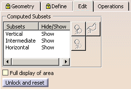
-
Make sure Full display of area is not selected.
-
Select the line of one subsets. The following icons become available:

deactivates contours in any subsets: - Click the icon, the dialog box disappears,
- Select the contour you want to deactivate. It is no longer displayed,
- Double-click anywhere in the viewer to revert to the dialog box.

reactivates contours of the selected subset: - Click the icon, the contours of the selected subset that have bee deactivated are displayed in dotted lines.
- Select the contour you want to reactivate,
- Double-click anywhere in the viewer to revert to the dialog box. The contour is visible again.

removes details in any subset: - Click the icon and select two points around the portion
to remove on the contour. A white line is displayed to visualize the
cut.
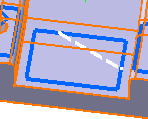
- Select the portion you want to remove,
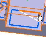
- A new closed contour is computed and displayed.
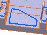

If other contours share the same area, the system proposes you to remove another portion. - Double-click anywhere in the viewer to revert to the dialog box.

- Those modifications are validated when you click OK in the dialog box.
- Click Unlock and reset to reset all the computations and editions: A message warns you that all modifications will be lost. Go to the list of subsets and perform a Hide/Show to redisplay the slope areas anew.
-
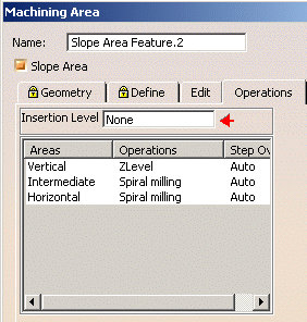
Go to the Operations tab.
Place your cursor in the Insertion Level box and select Manufacturing Program.1 in the tree.
The Assign Operation parameters are now displayed.
-
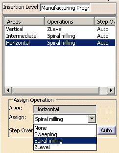
Click each area one after the other and use the Assign Operation box to assign:
- a spiral milling operation to the horizontal and sloping areas,
- a zlevel operation to the vertical areas.
-
Click OK.
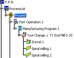
Three as-yet uncomputed operations are created in the specifications tree.
Each one includes the machining area you assigned it to.
-
Open the Manufacturing view and you will see that the machining area has been created along
with the operations assigned to it.
In the Manufacturing view:
- A slope area feature can be removed, using the
Remove Result
contextual menu.
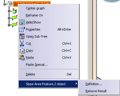
A message confirms the removal of the feature:
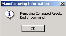
-
The Hide/Show item in the contextual menu does not work for machining zones
(zones created without the Slope Area option) .
Invalid Face
-
If a machining/slope area cannot be computed because of invalid faces,
an explicit warning message like this one will appear:

Each invalid face is highlighted in red, with an arrow pointing on it.
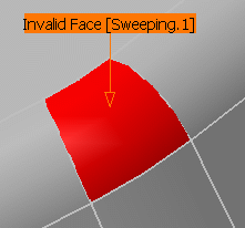
This visualization is removed when you close the main dialog box or
when you select Remove in the contextual menu.

![]()