 |
This task shows how to create
curves or points from a sketch (as designed using the Sketcher) or from
existing curves or points, onto a Sheet Metal part; and to
fold/unfold it, just as other Sheet Metal elements. |
|
This is especially useful when:
- you want to generate a logotype
- you want to define an area for chemical milling
- you want to create a cutout (pocket) to solve the overlapping of
walls for example (the overlapping can be checked with the
Check Overlapping functionality).
|

|
If you use Generative Sheetmetal
Design, open the
NEWMapping1.CATPart document. This sample already contains a
pre-defined sketch that will be mapped onto the part.
Otherwise, you would need to define a sketch by entering the Sketcher
workbench
 ,
selecting the wall onto which the curve should lie, and drawing the sketch
you wish. ,
selecting the wall onto which the curve should lie, and drawing the sketch
you wish. |
| |
 |
 |
-
Make sure the sketch is selected, and click Point or
Curve Mapping
 . .
The Unfold object definition dialog box is displayed,
indicating which elements have been selected for mapping.
In this dialog box:
-
The Add Mode button lets you add elements in
the object(s) list by selecting an element in the geometry or the
specification tree.
-
The Remove Mode button lets you remove
elements from the object(s) list by selecting an element in the
specification tree.
The curve mapping is previewed as if the supporting walls
were unfolded.
You can manage the list of objects if several are
available:
-
To remove an object, select it from the list and use
the Clear selection contextual menu.
-
To add an object, select it directly in the geometry.
Order in the list does not matter.
 |
The Support is not necessarily the support element on
which the element to be mapped has been drawn. Indeed, by default,
the Support is the last Sheet Metal feature that has
been created or modified, that is the current feature in the
specification tree. |
-
Select Wall.4 as the Support, that is the
element of the part on which the curve should be generated when folding
or unfolding.
The curve mapping is previewed as if Wall.4 was unfolded.
 |
You can select several support elements. To remove or replace
them, click the Multiselection icon and select the appropriate
support element.
|
-
Click OK.
The curve mapping is created and added in the
specification tree.
 |
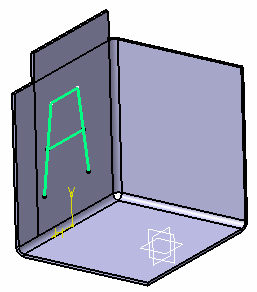
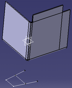
| Folded view of the curve mapping: |
 |
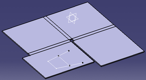
| Unfolded view of the curve mapping: |
 |
|
 |
- You can select several sketches/curves/points to be mapped at a time.
- Mapped curves can be created across several walls and bends.
|
|

|
![]()
