This task illustrates how to create a surfacic and a canonic hopper between two sketched profiles, with an opening line (for unfolding operations) defined by an edge for surfacic hoppers or two points for canonic hoppers.
Create a Surfacic hopper
Surfacic hoppers are defined by a ruled surface selected by the user or created thanks to the loft command. Defining a surfacic hopper via a loft is highly recommended since it allows detection of all canonical segments.
The two sketches used to define the loft can be on parallel or non parallel planes.
The reference wire and the invariant point, used to unfold the hopper, must lie on the surface, as well as the tear wire.
From a Ruled Surface
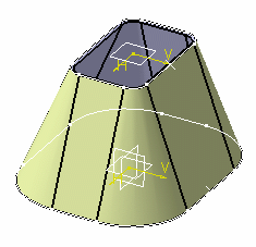
Open the NEWHopper01.CATPart document. This document contains two sketches, as well as a point on each sketch.
-
Click Hopper
 .
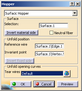
The Hopper dialog box is displayed.
.
The Hopper dialog box is displayed. 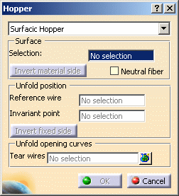
-
Right-click on No selection field and select Create Multi-sections surface.
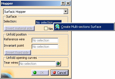
The Multi-sections Surface Definition dialog box is displayed. 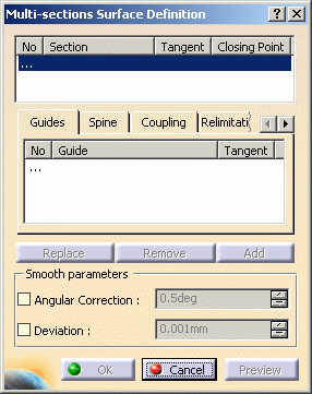
-
Select Sketch.1 and Sketch.2 in the specification tree as surfaces.

-
Click on the Coupling tab and start coupling sketches together by selecting points.
You should end up with eight couplings. 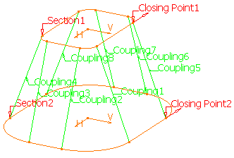
-
Click on Preview if you want to visualize the multi-sections surface, then on OK.
-
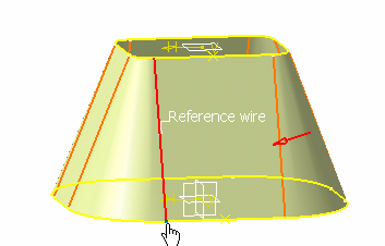
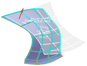
Select a reference wire lying on the surface of the hopper.
In our example, we select an edge. 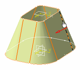
-
Select an invariant point lying both on the surface and on the reference wire.
A preview of the unfolded hopper is displayed, as well as its thickness in light blue. 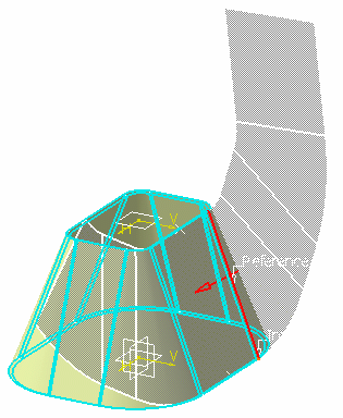
-
Select a tear wire.
In our example, we select the same edge as the reference wire.
The unfolded view of the hopper starting from the tear wire is displayed.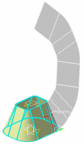

- A hopper can only be created if the surface is ruled.
- A hopper can only be created if the surface shows a tangency continuity.
- If you want to modify your selections in the Hopper dialog box, you can right-click in the field and select Clear selection in the contextual menu.
-
Click OK to validate and exit the dialog box. The hopper is created.
-
If you now click Fold/Unfold
 ,
the hopper is unfolded as follows:
,
the hopper is unfolded as follows: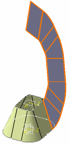
You can modify the hopper you are creating thanks to the options available in the Hopper dialog box.
-
Invert material side: the red arrow indicates the direction for thickening the hopper. You can change the thickening direction by clicking either this red arrow or the Invert material side button.
-
Neutral fiber: the selected input surface is considered to be the hopper neutral fiber. This option proves to be useful when the offset input surface is not ruled.
-
Reference wire: is an edge lying on the surface or a curve.
When you right-click on the Reference Wire field, you can select other types of reference wires.-
Create Line
-
Create Intersection
-
Create Projection
-
-
Invariant point: point lying on the surface and the reference wire.
When you right-click on the Invariant point field, you can create you own invariant point. -
Invert fixed side: the green arrow indicates the fixed side for unfolding: the hopper may be unfolded from the side opposite to the arrow. You can change the unfolding direction by clicking either this green arrow or the Invert fixed side button.
-
Tear wire: defines the opening line. It can be a curve going through the surface or several edges.
-
From a Double Curvature Surface
Open the NEWHopper02.CATPart document.
-
Click Hopper
.
The Hopper dialog box is displayed. -
Select a double curvature surface in the specification tree or directly from the geometry area.
A Reference Wire and an Invariant Point are automatically detected.
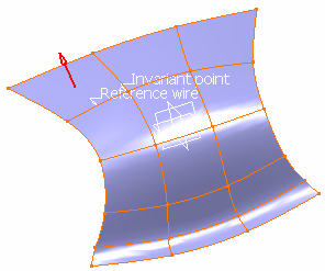
The Hopper dialog box is updated accordingly
You can modify the Reference Wire and the Invariant Point :- Click in the Reference Wire and Invariant Point field
- Select the reference wire and the invariant point directly in the geometry area.
-
Click the Preview button to preview the unfolded hopper.
-
Click the Display Distortions button to display the distortions using a color scale.
The Flattened Surface Length Distortions dialog box is displayed:
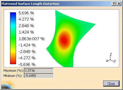
The distortion is only available if the initial surface is not ruled. If the initial surface is not ruled but its
offset is ruled then the distortion is not available. -
Click the Close button to close the Flattened Surface Length Distortions dialog box and go back to the Hopper dialog box.
-
Click OK to validate and exit the dialog box.
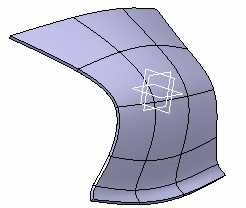
The hopper is created.
-
Click Fold/Unfold
.
The hopper is unfolded as follows:
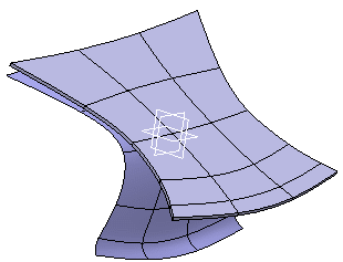
The symmetry of the result is not guaranteed. The symmetry might not be preserved.
Create a Canonic hopper
To sum up, each edge in a sketch must be an offset from a corresponding edge in the other sketch so that the resulting hopper may be conical, cylindrical or planar.
The two points defining the opening line (one point on each sketch) must have been created explicitly prior to creating the hopper. Each point should lie on a corresponding segment.
Open the NEWHopper01.CATPart document. This document contains two sketches, as well as a point on each sketch.
-
Click Hopper
.
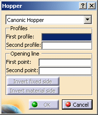
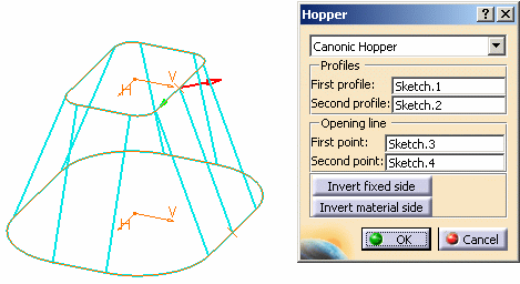
Select Canonic hopper in the Hopper dialog box that is displayed.
-
Select Sketch.1 as the first profile, either from the geometry area or from the specification tree.
-
Select Sketch.2 as the second profile.
-
Select Sketch.3 as the first point for the opening line.
-
Select Sketch.4 as the second point for the opening line.
- The green arrow indicates the fixed side for unfolding: the hopper may be unfolded from the side opposite to the arrow. You can change the unfolding direction by clicking either this green arrow or the Invert fixed side button.
- The red arrow indicates the direction for thickening the hopper. You can change the thickening direction by clicking either this red arrow or the Invert material side button.
-
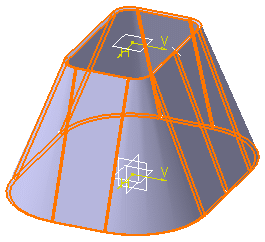
Click OK to validate and exit the dialog box. The hopper is created.
-
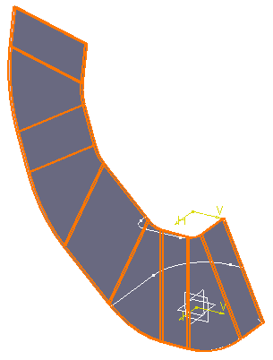
If you now click Fold/Unfold
,
the hopper is unfolded as follows:
|
|
Note that the first point of the opening must be on the first profile, and the second point must be on the second profile. |
A preview of the hopper is displayed. You can notice two
arrows starting from the first point.
 |
|
|
![]()