Mirroring a feature
- You can mirror a hole, a wall, a wall on edge, a cutout, a flange, a stamp (except stiffening ribs), a pattern or another mirror.
- Whatever feature you choose to mirror, it must lie on a unique, planar wall.
- It is mandatory that the result of the mirroring should lie on the part, otherwise it cannot be mirrored.
Open the NEWMirror01.CATPart document.
A cutout and a relimited flange are displayed on the wall.
![]()
-
Click Mirror
 .
.The Mirror definition dialog box is displayed. 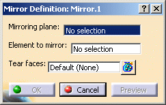
-
Select the feature to mirror, that is, Cut Out.1 in our example.

-
Select the zx plane in the 3D window as shown below.
The selected plane and a preview of the cutout to be mirrored is displayed. 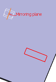
-
Click on Preview to visualize the mirrored cutout.
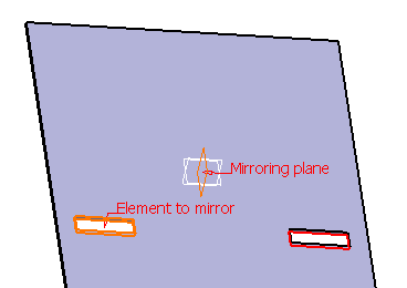

There are three different ways to select a mirroring plane:
-
In the 3D window, as in our example.
-
with a right-click on the Mirroring plane field in the Mirror definition dialog box.
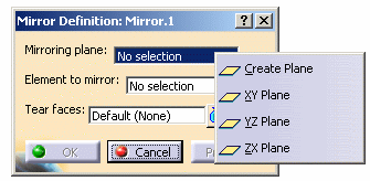
- with a right click in the 3D area.
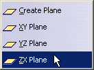
-
-
Click Ok to create the mirrored cutout.
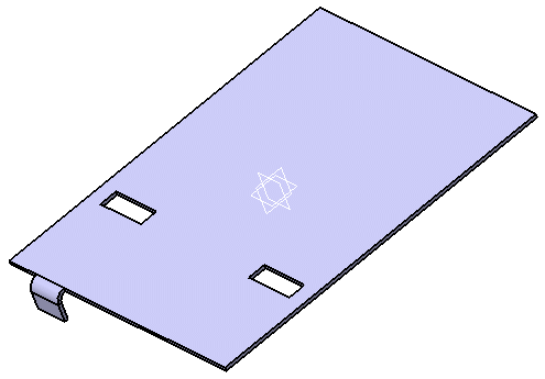

The mirror feature is displayed in the specification tree. If you selected the mirroring plane with a right click, the plane feature is also displayed in the specification tree, allowing you to double click on it should you need to edit it.
If you selected the mirroring plane with a right click, an icon is displayed in the Mirror definition dialogue box so that you can modify it if needed.
-
Select Flange.3.
-
Click the Mirror icon
 and select the zx plane.
The flange to be mirrored is displayed. 
-
Click Preview if you want to visualize the mirrored flange, then OK to create it.


When mirroring a flange, it is mandatory that the result of the mirror lie on an edge. 
The drafting of mirrored stamps and bends may be merged with the ones of the original features.
Mirroring a part
-
Click Mirror
 .
.The Mirror definition dialog box is displayed. -
Right-click on the Mirroring plane field and select Create Plane.


You can also define a lateral face of a part as the symmetry plane of the body. -
Create a plane as shown below.

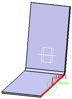
-
Click OK in the Plane Definition dialog box.
The preview of the mirrored part is displayed. 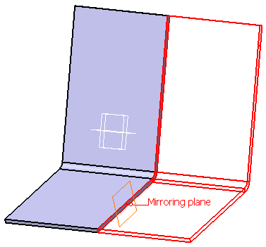
-
Click OK in the Mirror definition dialog box.
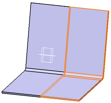

In some cases, the mirroring process may imply a connection of the result, as shown in the example below. 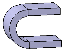
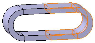
This case constitutes an ambiguity regarding the unfolding of the part. Consequently, a warning message is displayed and you have to select Tear faces.
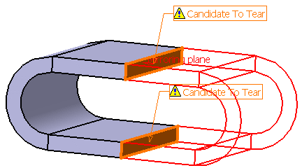
Tear faces define the opening faces: the way of unfolding the part depends on their selections.

To define tear faces:
-
Click Tear Face
 . A dialog box appears.
 - Select the face you want to become a tear face.
-
Click Close and click OK on the Mirror definition dialog box.
-
![]()