Extruding

This task explains how to create a wall by extrusion.
You can extrude sketches composed of lines, circles, projection of lines, and projection of circles. You can also extrude all kind of opened profiles.

You must have defined the Sheet Metal parameters.
A model is available in the NEWExtrude1.CATPart from the samples directory.

  1. Click Extrusion . The Extrusion Definition dialog box is displayed.

  2. Select a sketch.

    Several types of extrusion are available: 
    • Dimension : the requested input data are a sketch and a dimension,
    • Up to plane or Up to surface: a plane or a surface are input as limit to the extrusion. These functions are used to create walls that are not rectangular.
  3. Edit the Limit 1 dimension: and Limit 1 dimension: to set both extremities, for option Dimension.

    By default, the Limit 1 dimension: value is positive.
     

    The sketch you selected appears in the Selection field.
    You can now edit it by clicking the Sketcher icon if you wish to modify it.
    The Sketch at extreme position is active by default. You can set its position as middle by clicking Sketch at middle position .

  4. Define the options as needed:

    • Check the option Mirrored extent to extent the material on both sides of the sketch. In that case, only Limit 1 dimension: can be edited. 
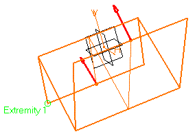
    This option is only available if the type is set to Dimension.

    • Push Invert Material Side to invert the direction of the creation of the material.
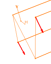
    You can push Invert direction to invert the extrusion direction.

  5. Click OK.

    The walls corresponding to the selected sketch are created according to the specified options, and added to the specification tree.
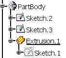
     

    You can check the option Exploded mode before clicking OK.

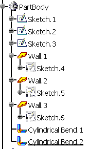
    Creating an extrusion can be just an acceleration of the design but very often it is just an intermediate state. It can be very convenient to explode the extrusion into several elementary features (wall , bend etc…) to enable modifications.


    • When the extrusion is the first Sheet Metal feature of the Part, the reference wall is the first wall created based on the first segment of the sketch.

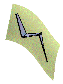
    • For option Up to Surface, while the wall end that is limited by the surface has the shape of the surface, its thickness does not fit the surface. It is a "rectangular" polygon defined by the first edge that comes into contact with the surface.


    • Such an extrusion can also be performed on a sketch made of lines and arcs of circle, provided there are no tangency discontinuities between the different elements. 
      However, in this case:

      • the Up to plane or Up to surface capabilities are not available, 

      • you cannot isolate such an extrusion,

      • if the element of the extruded sketch connected to the part is an arc of circle, the extrusion will not display in the unfolded view. To avoid this, prefer to create a User Defined Flange or remove the arc of circle of the extruded sketch and create a bend to connect the extrusion to the part.


    • Extrusion walls can be edited.

    The sketch may not be closed and it must contain at least a line.


Fixed Area

The fixed area is specified through a border vertex or an edge of the profile. CATIA proposes a default fixed geometry, but you can change it in the Fixed geometry selection box. 

Automatic Bend

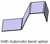
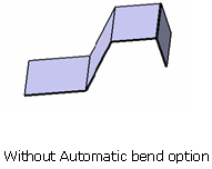
This option allows you to make fillets on sharp vertices of the profile. This option is activated by default.
         

KFactor Management

You can specify the KFactor for a bend coming from the extrusion of a circle contained in the sketch as well as for bend automatically computed. You can only specify a KFactor on a bend. To specify a KFactor you have to select geometry in the sketch that will lead to a cylindrical face. For a bend automatically computed you have to select the sharp vertex common to the two edges that will generate the fillet.

All the vertices or edges chosen for a specific KFactor value are put in the Bend geometry box. If there are several elements in the Bend geometry box, selecting the text symbol in the 3D will update automatically the Bend geometry box with the appropriate geometry.

For all the other bends if  no specification is  given the KFactor applied will follow the rule define in the Sheet metal parameters  (DIN if not deactivated) or will follow the bend table (if set in the sheet metal Thickness table).

If the extrusion contains non canonical edges (other geometry than lines or circles) the KFactor applied to the resulting face will always be 0.5.

Automatic Connection to the Sheet Metal Part
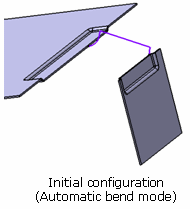
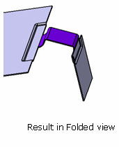
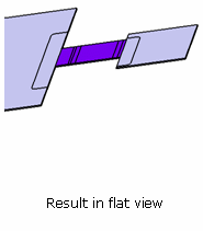
The Extrusion can now find automatically how to be connected to the sheet metal part and how to connect several volume of the part together. There is no option to make it happen.

The extrusion is connected when its lateral faces can be merged with a lateral face of the sheet metal parts. If an area of the extrusion is overlapping the sheet metal part it is not connected. If the extrusion has not been connected the warning message is displayed showing No Union has been done for that particular Extrusion.

If the extrusion is connected to the sheet metal parts the selection of a fixed geometry has no effect.
                   

Tears Selection

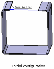
These allow you to control the union of the extrusion with the sheet metal part.

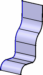
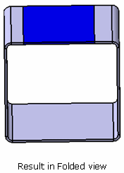
The profile and the resulting extrusion are colored in blue and you can see that you need to tear the sheet metal part to unfold it. The left edge has been selected as a tear face.
                   

  • The closed sketch is not allowed for extrusion creation.

  • The sketches for the sub extrusions are under-constrained.