Open the NEWWall1.CATPart document from the samples directory.
-
Click Wall on Edge
 and select an edge of the wall.
 -
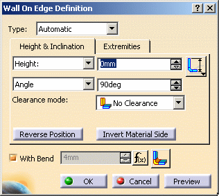
Specify the following references:
- the Length type of the wall
you want to define
Select: - the
 icon to define the height of the wall from the bottom of the
reference wall,
 - the
 icon to define the height of the wall from the top of the
reference wall,
 - the
 icon to
define the height of the wall from the top of
the bend,
 - the
 icon to
define the height of the wall from the intersection between
the bottom of the reference wall and the bottom of the wall
on edge.
- the
- the Length of the wall: that is the absolute value of the wall on edge without bend.

You can also define the height limit of the wall on edge with a plane or a surface by selecting Up to Plane/Surface in the Height box. If you need to create a plane, right-click the limit field.Click Limit position
 to define whether the height limits are to be
defined on interior or
on exterior of the wall on edge.
When the Height limit is selected, the offset value is the height of the wall from the top of the bend (Third length type).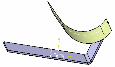
On interior
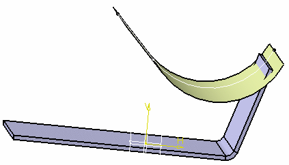
On exterior

You can also define these parameters with a right-click on the annotations. - the Length type of the wall
you want to define
-
Define the width of the wall by entering right and left offsets.

You can also define the width limits of the wall on edge with planes or surfaces. If you need to create a plane, right-click the Left limit or Right limit fields. 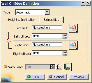
Click Limit position  to define whether the width limits are to be defined on
interior or on exterior of the wall on edge.
In Automatic mode, you can swap the left limit with the right limit using Swap limits  .
. -
Define the angle of the wall: by default it is perpendicular to the plane containing the edge. You may modify it according to your needs. It is dynamically updated on the screen.

You can also design a wall on edge using a predefined support by selecting Orientation plane. If you need to create a plane, right-click the Default support field.
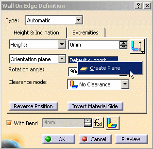
Angle and clearance values become relative to the selected plane.

You can define tangent walls (angle value = 180°). -
Select a Clearance mode to offset the wall on edge from the selected edge according to your needs and enter a Clearance value.


- The No Clearance mode allows you to define a wall on edge without clearance.
- The Monodirectional mode allows you to move the wall in one direction.
- The Bidirectional mode allows you to move the wall in two directions.

A warning is displayed if you choose Bidirectional mode. Indeed, this clearance mode implies a relation created through the formula, between the wall position and the sheet metal parameters bend value. Consequently, after designing your part, the wall position will change if you modify the sheet metal parameters bend value.
-
Choose to create the wall with or without a bend by checking the With Bend option.

You can edit the bend properties by clicking Bend parameters  or by right-clicking the extremities annotations.
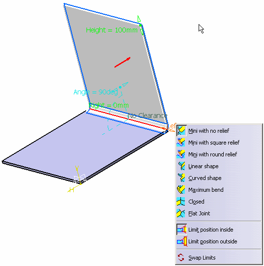

- If there is no wall from which a limit can be computed, the reference element is the edge of the reference wall.
- A wall on edge is defined by the selected edge (reference
edge). When the reference edge is modified, by adding any feature
that shortens the edge (a bend to an adjacent wall on edge or a
cutout for example) the wall on edge based on this reference edge
is recomputed.
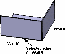
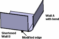
- To avoid this you may:
- create the bend manually on the wall modifying the edge used as the reference to create the other wall
- reorder the creation of walls to postpone the creation of the modifying feature
- Both limits are computed with the same reference icon.
- The bend is not previewed, even if the option With Bend is checked. However it will be created.
- The selected options are modal and will be proposed to create the next wall.
- Walls on edge being contextual features, if you break the profiles continuity by inverting the material side of a wall, you may have to manually re-specify all features based upon the modified one, even if they are not directly connected to the modified wall, in order to update the part afterwards.
This is the case when creating a wall on edge from another wall on edge, for example: 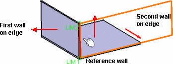
- If you invert the material side of the reference wall on which
the first wall on edge has been created, both walls on edge are
relocated (as if you were flipping the geometry):
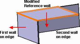
- If you invert the material side of the first wall on edge (and
not the material side of the reference wall), the second wall on
edge is relocated. Indeed, its specification being relative to the
first wall on edge, when its input data (i.e. the edge selected on
the first wall on edge) is modified, the second wall on edge is
rebuilt at a new location.
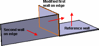
-
If necessary, modify the support geometry by extrapolating it. This extrapolation is automatically computed.
There are two kinds of extrapolation : -
 : extrapolation
based on the geometry of the wall on edge support.
  : extrapolation based on the geometry of the wall on edge.
-
-
Click OK in the Wall On Edge Definition dialog box.
A WallOnEdge.xxx element is created in the specification tree. 
- A WallOnEdge.x element can be edited: double-click it in the graphic area or in the specification tree to display its creation dialog box and modify the parameters described above, including the edge from which it is created. However, the sketch of a wall on edge cannot be edited directly.
- You can cut or copy and paste a wall on edge.

- If you cut and paste a wall on edge with children elements, these children elements are lost. This may result in update errors.
- You cannot undo an Isolate action after having modified the wall.
- Isolating a wall on edge erases all updating data.
Creating a Wall On Edge from a sketch
-
Click Wall on Edge
 and select Sketch based in the
Type field.
 -
Select an edge of the wall and click Sketcher
 next to the Profile field.
 -
Select a plane and click Profile
 .
. -
Sketch the profile.
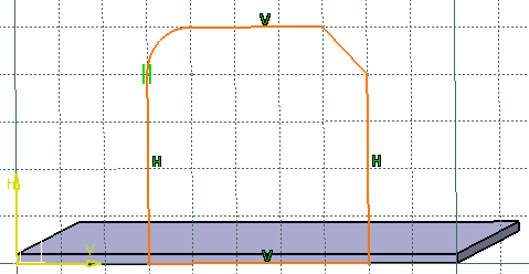

- When an extrapolation is necessary during the
cretion of a sketch based, the wall profile must intersect
the plane represented by the selected edge and the top or
bottom face.
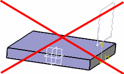
- When the extrapolated mode is active, the cutting edges of bend extremities can only impact the extrapolated wall.
- The sketch based wall profile must only create one face.
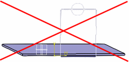
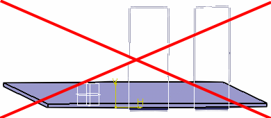
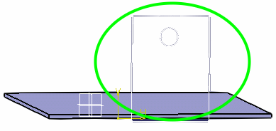
- When an extrapolation is necessary during the
cretion of a sketch based, the wall profile must intersect
the plane represented by the selected edge and the top or
bottom face.
-
Click Exit workbench
 to return to the 3D world.
The wall on edge is previewed. 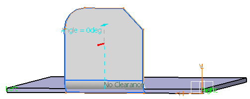
-
Click OK.
Creating a Wall On Edge on a Flange or a Stamp
Let's take an example with a user flange.
-
Click Wall on Edge
 and select the edge of the user flange.
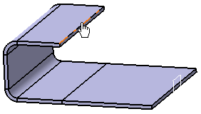
-
Click OK in the Wall on Edge Definition dialog box to create the wall on edge on the user flange.
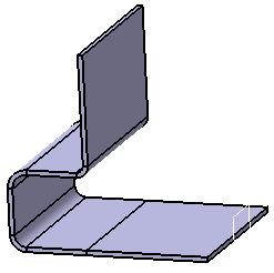
![]()
