![]()
![]()
You must be in the Sheet Metal Workbench, with a .CATPart
document open, and you must have defined the
sheet metal parameters.
Set the sketcher grid to H = 100mm and V = 100mm,
using the Tools -> Options, Mechanical Design -> Sketcher,
Sketcher tab.
![]()
-
Click Sketcher
 then select the xy plane.
 -
Click Profile
 .
. -
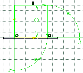
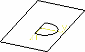
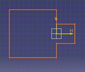
Sketch the profile as shown below:
-
Click Exit workbench
 to return to the 3D world.
 -
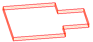
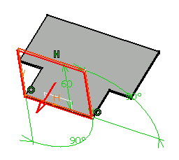
The Wall Definition dialog box opens. 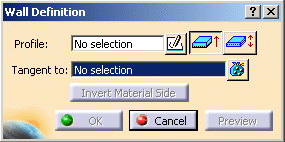

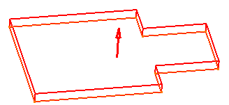
By default, the Material Side is set to the top.
-

-
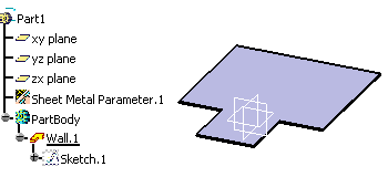
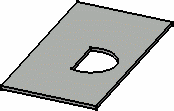
Click OK.
![]()
