This task shows how to create the sheet metal part views in the Generative Drafting workbench.
The sheet metal part is displayed.
-
The Generative Drafting
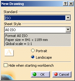
 workbench is launched. The New Drawing dialog box opens.

-
Click OK.
For more information about this workbench, refer to Generative Drafting User's Guide.
-
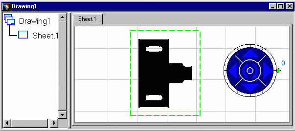
The drawing sheet appears.
-
Tile the windows horizontally using the Window -> Tile Horizontally menu item.
-
Select the Unfolded View icon
 in the Projections toolbar from Generative Drafting Workbench.
-
This icon is added to the Projections toolbar provided the Sheet Metal workbench is present.
-
Choose the xy plane in the Sheet Metal specification tree. The unfolded view is previewed.
-
Click in the drawing to validate and generate the view, with the bend axes and bend limits when applicable.
![]()
