- open a sketch on an existing face
- define a profile in order to create a cutout.
-
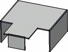
Select Wall On Edge.2 from the geometry area to define the working plane.
-
Click the Sketcher icon
 .
.

-
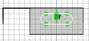
Click the Elongated Hole icon
 to create the profile.
-
To access the oblong profile, click the black triangle on the Rectangle icon.
It displays a secondary toolbar.

-
Click to create the first point and drag the cursor.
-
Click to create the second point.
The first semi-axis of the profile is created. -
Drag the cursor and click to create the third point.
The second semi-axis is created and the oblong profile is displayed.

-
Click the Exit workbench icon
 to return to the 3D world.
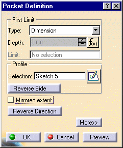
The Pocket Definition dialog box is displayed and a cutout is previewed with default parameters.

-
Set the Type to Up to last option to define the limit of your cutout.
- This means that the application will limit the cutout onto the last possible face, that is the opposite wall.
-
Click OK.
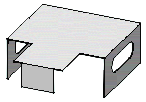
- This is your cutout:

![]()