 |
This task shows you how to add other walls to the
sheet metal part. |
 |
-
Click the Wall on Edge
icon  . .
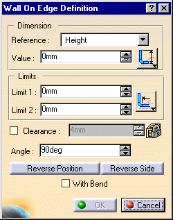
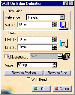
The Wall On Edge Definition dialog box opens.
-
Select the left edge.
-
Enter 50mm in the Value field.
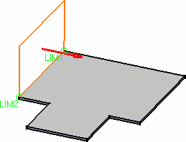
The application previews the wall.
|
 |
|
 |
 |
By default, the material side
is such that it ensures a continuity with the reference profile. If needed,
invert it using the Reverse side button, or clicking the arrow. |
|
-
Click the Reverse Position button to Invert
the sketch profile.
-
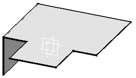
Click OK.
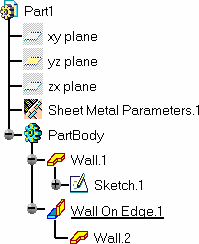
The wall is created and the Wall On Edge.1 feature is
displayed in the specification tree:
|
|
 |
 |
|
-
Select the right edge.
-
Click the Wall on Edge icon  again.
The Wall On Edge Definition dialog box opens with the parameters
previously selected.
-
Invert the sketch profile and click OK to
validate.
|
|
-
Click the Wall on Edge icon  again.
-
Select the front edge.
The Wall Definition dialog box opens with the parameters previously
selected.
-
Enter 30mm in the Value field and 10mm in the
Limit1 and Limit2 fields, then invert the sketch
profile.
-
Press OK to validate.
|
 |
|
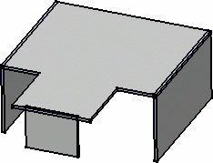
The final part looks like this:
|
|
 |
|

|


