Creating a cutout consists in extruding a profile and removing the material resulting from the extrusion.
Open the Cutout1.CATPart document.
-
Click the Cutout icon
 .
. -
Select a profile.
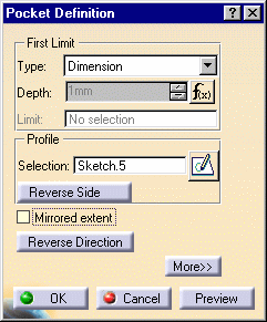
The Pocket Definition dialog box is displayed and CATIA previews a cutout with default parameters.
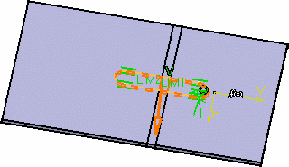
Once the sketch is
selected, you can modify it by clicking the Sketcher icon
![]() .
.
-
Select the type.
Several limit types are available:
-
Dimension: the cutout depth is defined by the specified value
-
Up to next: the limit is the first face the application detects while extruding the profile. This face must stops the whole extrusion, not only a portion of it, and the hole goes through material.
-
Up to last: the last face encountered by the extrusion is going to limit the cutout
-
Up to plane: the cutout is limited by the selected plane
-
Up to surface: the cutout is limited by the selected surface
When an Offset value is required, it is the distance between the limiting element and the top face of the cutout, if the latter does not result in a complete hole through the material.
The LIM1 and LIM2 texts in the geometry area indicate the top and bottom limits of the cutout.
-
The Reverse Side option lets you choose between removing the material defined within the profile, which is the application's default behavior, or the material surrounding the profile.
- The Reverse Direction option allows you to invert the direction of the extrusion pointed by the arrow.
-
Click OK in the Pocket Definition dialog box.
The cutout is created.
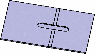
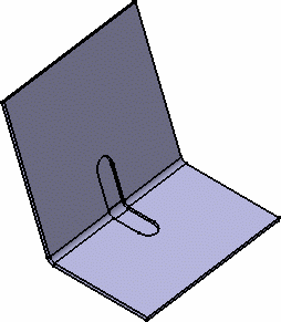
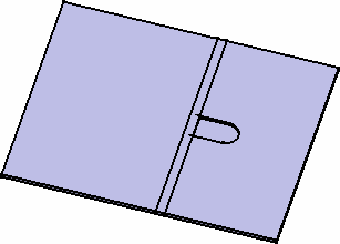
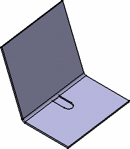
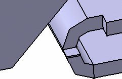
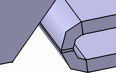
-
Click More>> to display the maximum information.
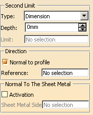
- You can define 'Limit2' as the second limit by using the same options as for Limit 1 (Dimension, Up to last, up to plane, up to surface).
- You can choose between a direction normal to the profile or define a new direction by selecting geometry in the Reference field.
- You can choose the cutout to be normal to the sheet metal part: check the Activation button and define the sheet metal side.
-
Select the Support (here we chose the wall)
- Refer to the Component Catalog Editor documentation to have further information on how to use catalogs.
- Refer to the Pocket task in the Part Design User's Guide for further details on how to create cutouts.
![]()