![]()
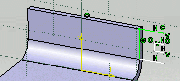
This task shows how to create a wall tangent to a planar part of another wall or of a flange. This capability will then allow this tangent wall to be seen when unfolding the part, even though there is no bend linking it to its tangent support, provided this support is unfoldable too.
![]()
Open the TangentWall1.CATPart document from the samples directory.
![]()
-
Select a face of an existing wall and click the Sketcher icon
 .
.
Here we selected the flange's planar face.
-
Select the Profile icon
 and sketch the profile as shown below.
-
Using the Constraint Defined in Dialog box icon, set coincidence constraints between the edges where the support and sketch are to coincide.
-
Click the Exit workbench icon
 to return to the 3D world.
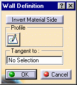
The Wall Definition dialog box opens.
-
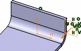
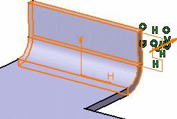
Click inside the Tangent to field, then select the wall to which the new wall has to be tangent.
Here, you need to select the planar face of the flange.
-
Click OK.
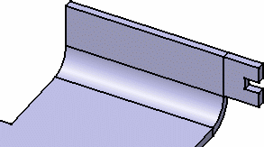
The wall is created and a Wall.xxx feature is added in the specification tree.
-
Click the Unfold icon
 .
.
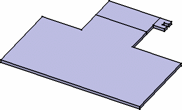
The tangent wall is unfolded as a wall linked by a bend to another wall, would be.
![]()
If you want to create the wall on a wall that cannot be unfolded, the system issues a warning and prevents you from creating the tangent wall.
![]()
