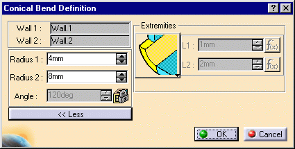
These bends are different from the standard bend in that they allow different radius values at each end of the bend.
Open the ConicalBend1.CATPart document from the samples directory.
-
Select the Conic Bend icon
 .
.
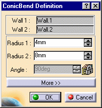
The Conic Bend Definition dialog box opens.
-
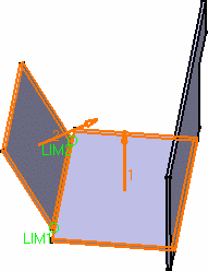
Select Wall.1 and Wall.2 in the specification tree or in the geometry.
The Bend Definition dialog box is updated, and arrows are displayed indicating the walls orientation.
You can click on the arrow to invert them if needed.
The LIM1 and LIM2 texts indicate the endpoints for the bend.
-
Enter the radius values for each end of the conical bend.
If the difference between the specified radius values does not allow the generation of a cone with an angle greater than 1 degree, a warning is issued prompting you to increase one of the radii.
Click OK in the Warning dialog box, and increase/decrease the radius values.
By default, Radius 2 is twice Radius 1.
-
Click More... to display further options.
-
Choose the bend extremities:
-
Mini with no relief: the shortest possible bend is created, and presents no relief
-
Curve shaped: the bend is created keeping the tangency continuity with the support walls.
-
Maximum: the bend is calculated between the furthest opposite edges of the supporting walls.
-
Click OK.
The Bend is created.
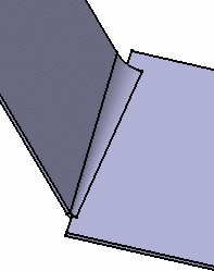
- The two walls must be connected by the edge of their internal faces.
- The Angle field is locked. It indicates the angle value between the two walls between which the bend is computed.
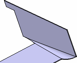
- Should you choose the Curve shaped extremity option, the bend would look like this:
![]()
