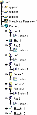
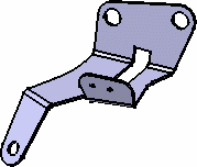
This document contains a part created in the Part Design workbench and looking like this:
-
Select any face of the part.
-
Click the Walls Recognition icon
 .
.
-
Choose the Wall creation mode:
-
Part body recognition: the whole solid is processed and walls are created wherever possible
-
Only selected faces: only explicitly selected faces of the solid are processed and the corresponding walls are created.
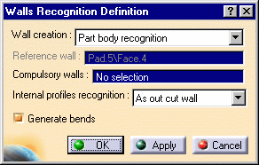
The Reference wall is indicated in the Walls Recognition Definition dialog box for information only (it is grayed out).
-
Select faces as the Compulsory walls.
These are faces from which the walls are to be generated when there might be an ambiguity. For example, if the initial part is a box, you will need to select two opposite inner faces and outer faces on the other two sides of the box, in order to avoid overlapping when generating the walls.
-
Set the Internal profiles recognition mode:
-
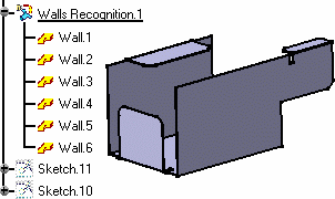
As cut out wall: generates walls with inner profiles (no cutout feature is generated)
- One cut out by wall: regardless of how many pockets there are on a face of the solid, only one cutout feature is generated per wall
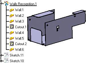
- One cut out by profile: for each inner profile on the sketch-based solid, a cutout feature is generated
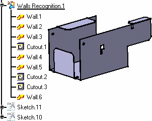
- None: whether there are pockets on the solid faces, or not, no cutout feature is created in the resulting SheetMetal features.
The Generate Bends check button allows the automatic creation of bends as the walls are being created, wherever applicable.
-
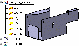
Click OK to generate the walls, and bends if any.
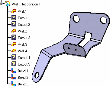
Walls are automatically generated from the Part Design geometry.
This part contains a filleted CATIA V4 solid presenting different orientations.
-
Click the Walls Recognition icon
. -
Click any face of the part as the reference wall.
The Wall Recognition Definition dialog box is displayed. -
Make sure the Generate Bends button is checked.
It allows the automatic creation of bends, wherever applicable, as the walls are being created, .
Walls and bends, due to the presence of fillets in the initial part, are automatically generated.
Double-click the Sheet Metal Parameters entry from the specification
tree to see them.
The Thickness parameter cannot be modified because it is based,
like the bend extremities and radius, on the initial solid geometry .
However you can modify these parameters (bend radius and bend extremities)
to be taken into account for sheet metal features other than the
"recognized" ones.
The bend allowance, being used to unfold the part, and the corner relief
affect all features, and therefore can be edited even for "recognized"
features.
Uncheck the Generate Bends button, if you do not wish bends to be created automatically.
![]()