 |
This task explains editing of a planning break. |
 |
Editing planning breaks adds offsets that increase the structural strength
of the ship assembly. Two kinds of planning breaks are managed by this
application. As a result you may see a point or a curve in the display.
- A profile planning break results from an
intersection between the face of a functional volume and the trace of a
profile. The result is a geometrical point, seen as an X.
- A plate planning break results from the
intersection between the face of a functional volume and the molded
surface of a plate. The result is a geometrical curve.
|

|
1. |
With your
document open, enter the Objects workbench. Right click on the planning
break and select XXXObject - Definition in the drop down menu.
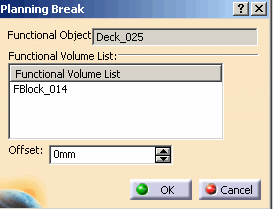
The Planning Break dialog box opens with the following
information:
- The functional object the planning break belongs
to;
- The list of functional volumes the planning break
was generated from. This cannot be edited;
- The offset value. The manipulator (the green arrow
in the image) will move by the value entered in the Offset
field.


|
| |
2. |
Enter a value
in the Offset field and click OK. The offset you entered will be applied to
the planning break. You can select more than one functional volume to edit.
 |
| |
3. |
Click OK
to accept or Cancel to exit the command. |


