Beam Creation

This task takes you through a simplified process of creating a point-to-point beam. More information about this, and about creating pillars and other types of beams, is provided in the section Creating Beams and Pillars.
The process of creating beams and pillars is essentially similar. Both beams and pillars are placed at the same level as the plates in the specifications tree.

The image below shows beams created by using pillar extremities.
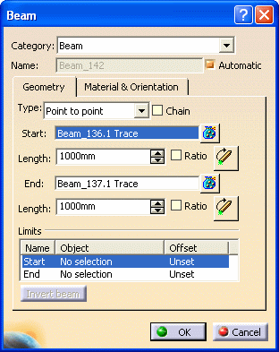


1. With your document open, click the Beam button to open the Beam dialog box.

The fields will differ based on the Type selection. The image above is for the Point to Point type.

  2. Select Beam in the Category field, and check the Automatic checkbox.
  3. For Type, Select Point to Point.
  4. In the Start and End fields, select a position along the support curve of an existing beam. You can do any of the following:
  • Select the extremities of existing beams. (When your selection point is near the start, mid, or end point of a beam, these points become your selection point. However, you can select specific offset values.)
  • Select a point in your 3-D session, or a point on the plane system grid. (Make sure the Selectable Points checkbox is selected on the Plane System Grid dialog box.)  If you select the Chain checkbox, you can select as many points as necessary. The last end point selected becomes the start point of the next beam.
  • Right-click and select from the list of GSD stacking commands.

You see the beams display in your 3-D session as you make your selections.

  4. Enter information in the other fields as required. Click OK when you are done.