 |
This task explains how you can create a simplified representation of a
section. |
 |
Sections used in this application do not display any 'thickness'. Display
of thicknesses is not necessary at this design stage and displaying
sections in this manner improves performance. (However, thickness
information can be stored with the section for use in downstream
processes.) In order to use sections for use with this application you need
to create a simplified representation, which is explained here. |

|
1. |
Open the
section for which you want a simplified representation in the Sketcher
application. Make sure that the option Construction/Standard Element
is not set - this is controlled through a button
 in the Sketch
Tools toolbar. in the Sketch
Tools toolbar.
 |
 |
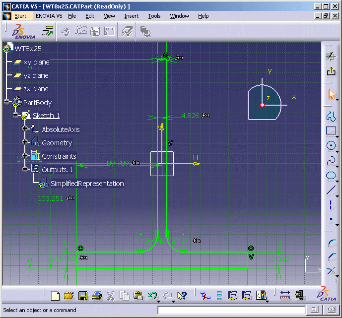
Sections whose
webs will be welded to the plate - L, T, FL and Bulb sections - need an
additional step, explained here. Rename the left, center and right points
of the web section as shown below. This allows the section to locate
correctly when placed on a plate. Rename:
- Left - catStrWebSideLeft
- Center - catStrWebCenter
- Right - catStrWebSideRight
|
| |
2. |
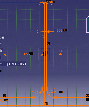
Using a
Sketcher tool (for more information on using the tools see Sketcher
documentation) draw two lines that represent the simplified version of the
section. The lines can be drawn anywhere you want in the section, but note
that the section will be placed according to the placement of your lines.
In the image below the lines (displayed thicker than the rest of the
section) have been drawn along the center, and bottom, of the section,
which is usually appropriate for this type of section.

NOTE: If you are creating a new anchor point -
meaning creating an anchor point on geometry that does not exist - then you
must make sure that the option Construction Element is set.
This option is referenced in Step 1. |
| |
3. |
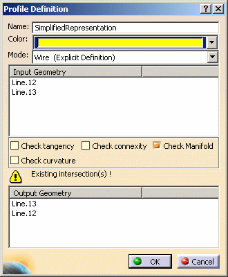
Select the
lines you created and, in the Tools toolbar (often located at the bottom of
the window), click the Profile Feature button
 . The Profile
Definition dialog box displays. . The Profile
Definition dialog box displays.

- In the
Name
field enter SimplifiedRepresentation.
- Change the color of the lines. The color used in
the sample sections is yellow.
- Click the down arrow in the Mode field
and select Wire (Explicit Definition).
- Make sure that the Check Connexity
checkbox is not selected.
- Click OK.
|
| |
4. |
The simplified
representation displays in the specifications tree. Save the CATPart. |


