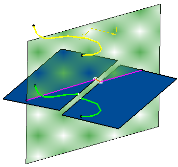
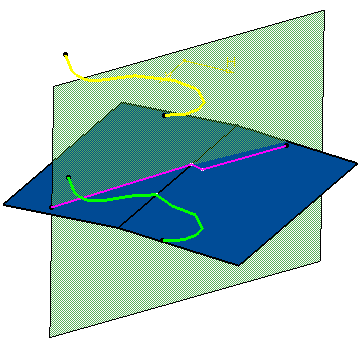
Here is the standard visualization: all surfaces and wires are continuous and there is no visible gap.
-
Click WYSIWYG mode
 .
.The standard visualization switches to the WYSIWYG visualization: 
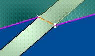
Gaps are now visible and a junction edge has been created. It is created when a wire lying on a surface crosses a gap of the surface. It is represented by a dotted line and its extremities are materialized by two concentric circles (providing you selected a current view mode that displays edges). 
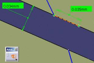
In the case of a creation operation of a wire on a shell, a junction edge is created if and only if its length is bigger than the size of the gap: 

The junction edge is created The junction edge is not created
- When activated, the WYSIWYG mode icon remains highlighted as long as the wysiwyg visualization mode is activated. To come back to the standard visualization mode, just click the icon again.
- The wysiwyg command is shared, which means that it can be selected while another command is already running without interrupting it.
- The wysiwyg mode applies to all the documents opened in the session, not only to the current part.
- While in the command, Hide/Show and Swap Visible Space commands are available.
- While in the command, the Graphic Properties toolbar and the Edit Properties command are not available. Therefore, properties such as Color, Linetype, Thickness, Layer etc. cannot be modified while working in the wysiwyg mode.
- The wysiwyg command is cancelled:
- when creating a feature,
- when an exclusive command is launched
- during File/Open, Save, Close and Update operations,
- when changing the active window or the workshop
-
The wysiwyg mode is compatible with measures, but only the Picking point and Picking axis selection modes are available.
![]()
