If you are working in a CATPart, the dialog box looks like this:
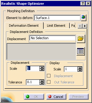
If you are working in a CATProduct context and have activated a CATPart, the
dialog box looks like this:
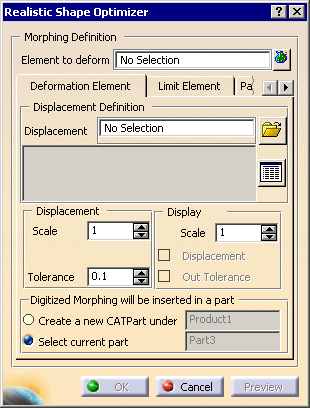
The Digitized Morphing parameters are displayed in three tabs:
- Deformation Element,
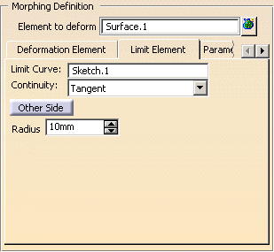
- Limit Element,
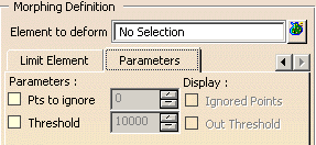
- Parameters.
Element to deform
If you are not using a limit curve, you can select several elements to
deform (multi-selection is available).
If you are using a limit curve, only one element can be processed.
Deformation Element tab
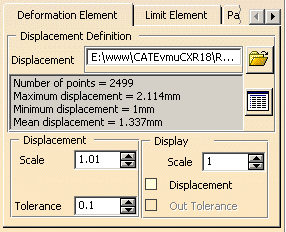
![]() lets you browse the directory to select one or several files containing the
displacement vectors.
lets you browse the directory to select one or several files containing the
displacement vectors.
Their names and paths are displayed in the Displacement field.
![]()
- displays the list of files selected,
- resets your selection,
- removes files from the selection.
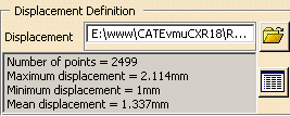
Statistics are displayed in the text field on the left. They pile
up as you go on.
Displacement

Those parameters affect the computation.
Applies a coefficient on the vector to increase or reduce the
displacement.
If you enter a negative scale, the displacement is computed in the opposite
direction.
Press Preview at each modification of this parameter.
Scale=1


Scale=-5
 Tolerance
The tolerance can be represented by a sphere centered on each ideal deformed
point.
If the actual computed point is not within the tolerance sphere, it is
ignored.
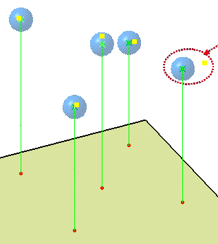
Press Preview at each modification of this parameter.
Display

Those parameters affect the display.
you may wish to use the option
Display all elements using Z-buffer depth in Tools>Options>Display>Visualization.
Select Displacement to display the vectors:
- the original points are displayed in blue,
- the output points are displayed in red,
- the vectors are displayed in green.
Applies a coefficient on the vectors to increase or reduce their display length.
Scale=1

Scale=5
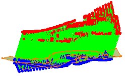
Becomes available after a Preview action.
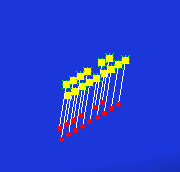
Displays the points that do not meet the tolerance as follows:
Limit Element Tab
Limit Curve
You can select only one curve, open or closed, as the Limit Curve.
It must lie on the surface to deform, and divide this surface in two
distinct sides.
A contextual menu is available to clear the selection.
![]()
Continuity

Defines the type of continuity between the output surface and the limit curve.
Other Side
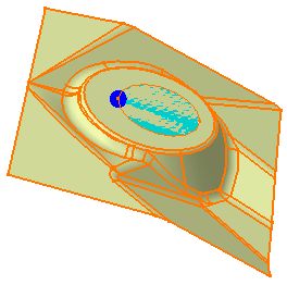
Once the Element to deform and the Limit Curve are selected, the area to deform is highlighted in blue. Other Side lets you process the area located on the other side of the Limit Curve. The highlight is updated accordingly.
Radius
Lets you define the radius of a circular pipe centered
on the limit curve, within which points are removed.

This radius is visualized as a dark blue sphere (we set it to 2).
Parameters tab
Exact percentage of points that will be
ignored.
The points ignored are those with the greatest distance between the ideal
computed point
and the actual computed point.
Becomes available after a Preview
action.
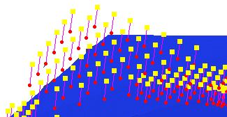
Displays the points that are ignored as follows:
Defines the greatest allowed displacement. Points with a displacement
exceeding this value are left out.
When you select a vector file, this value is initialized with the greatest
displacement computed from this file.
You can then enter a smaller value.
Becomes available after the selection of
Threshold.
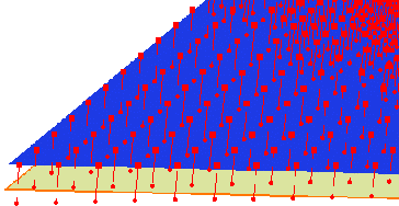
Displays the points that do not respect the threshold as follows:
![]()
