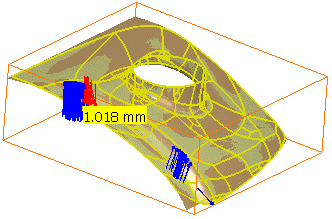
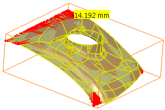
- The Automatic Surface command is adapted to many types of shapes.
- It can create complex surfaces with a minimum set of Nurbs.
- It can take holes into account.
- It preserves fillet with small radius (but not very sharp edges).
- Surfaces can be created with or without a full internal tangency between faces.
The input required is a mesh (not a cloud of points):
- it may not have non-manifold vertices or triangles,
- it must be a mono-cell mesh, without non-connex zones,
-
Click Automatic Surface
 .
.
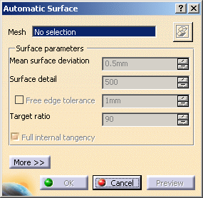
-
Select Sample as the Mesh. The
 is now available and enables you to hide or show the mesh.
 -
Type the Mean surface deviation,
i.e. the average deviation between the surface that will be created and the input mesh,
computed on all mesh vertices. -
Click Preview to preview the surface.
-
Click More to have access to statistics and some display check boxes:
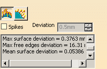
The Statistics are:
- output faces:
global count of faces contained in the output surface,- Max surface deviation:
value of the maximum deviation between the surface and the mesh,
also displayed with the spikes,- Max free edges deviation:
value of the maximum deviation between the free edges and the mesh,
also displayed with the spikes,- Mean surface deviation:
value of the mean deviation between the surface and the mesh,- xx% of yyy points Ok:
percentage of the measured points that are under the Mean surface deviation.
-
Select the Spikes check box to visualize the deviations between the mesh and the surface:
- The points with the maximum deviation on the surface or
on free edges are displayed on a small yellow rectangle,
with the corresponding value of the deviation.- Deviation enables you to display only the spikes on points
with a deviation greater than this value.- Negative and positive deviations are displayed in different colors.
- Click
to visualize the deviations on the surface:
- Click
to visualize the deviations on the free edges
(only availbable when free edges exist):
-
Click OK. Surface.2 is created.
Tuning parameters
Surface detail
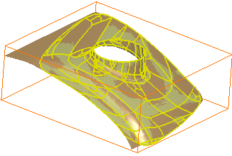
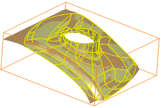
Helps you increase or decrease the respect of mesh details on the
resulting surface:
the higher the value, the higher the respect of details.
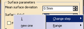
The proposed range value is just an indication. It can be edited through
its contextual menu:
 |
- The Surface detail is set to 500:
- The Surface detail is set to 1000:
Free edge tolerance
Chordal value used to sample the mesh boundaries.
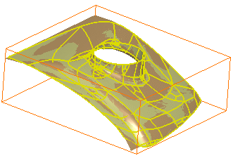
Select this check box to improve the quality of the surface with respect to the mesh boundaries.
- Free edge tolerance is not selected:

- Free edge tolerance is selected:
Target ratio
Ratio of measured points with a surface deviation under the Mean surface deviation value.
- The actual ratio obtained may be different (greater or lower) than the one you have requested.
- A ratio next to 100 is time consuming.
the surface is created and a message is displayed.
Full internal tangency
By default, this check box is selected and provides a full internal tangency between the faces of the output surface.
If full internal tangency is not mandatory, you can clear this check box. The output will be smaller in term of memory size and control points. However, you will not be able to recover full internal tangency later on, e.g. with healing or filleting commands. Nor will you be able to perform thickness or offset operations on the output surface.
![]()
