(The color of the curves have been changed to several shades of blue in the picture below).
In some cases (especially with long curves) the chaining may lead to an unexpected result.
You may need to slice curves or edges in order to solve this chaining incompatibility.
-
original curves: clean contour impossible
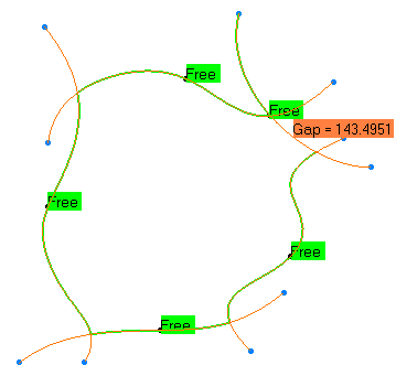
- sliced curves
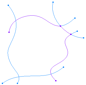
-
clean contour
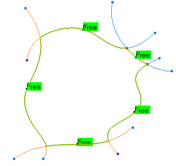
The Curves Slice action cuts curves or edges in several
pieces, according to a pseudo-intersection:
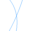
there is a pseudo-intersection between two curves if they intersect each
other in the view direction
(but not really), and if the mini 3D distance between them at this cutting
point is lower than the
parameter Max. Distance.
- Pseudo-intersection of two curves in the view direction
 |
- in another view.

in the picture below, the arrows point at the minimum distance between the 2 curves.

-
Activate the Geometrical set using the Define in Work Object contextual menu.
-
Click Curves Slice
 .
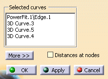
The Curves Slice dialog box is displayed.
 -
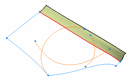
Select the curves or the edges to slice.
The list of the selected curves or edges is displayed in the Selected curves field.
You can remove an element from this list by selecting it again.
You can then resume the selection of the elements.
-
Click Apply. The resulting segments and the cutting point on each curve are pre-visualized.
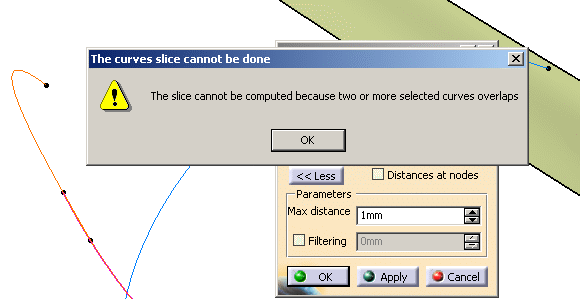
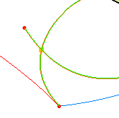
Curves overlaps are detected automatically and displayed in magenta:
There is no information message, no distance label, only a yellow square:
the curves do intersect each other.
A message may inform you that the curves or edges do not "pseudo-intersect"
each other with respect to the Max distance parameter.
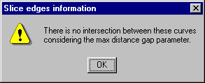
These curves do not intersect each other, whatever the Max distance parameter.
There is no solution.
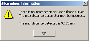
The curves will intersect each other if you set the Max distance parameter to
a value higher than that indicated in the message. -
Click More >> to display the Max distance parameter: Its default value is 1mm.
Max distance is the minimum orthogonal distance between two curves above which
one considers the two curves do not "pseudo-intersect" each other.
Increase this value according to your needs and click Apply.

-
By default, the Distances at nodes are not displayed.
When this check box is selected, the Distances at nodes
(i.e. the mini 3D distances between the two curves of a pseudo-intersection)
are displayed in yellow with the exception of the largest one that is displayed in black.
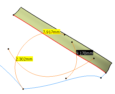
Double-click this black label to update automatically the value of Max distance
in the dialog box, with a slightly higher value. -
Very tiny segments may be created.
To avoid it, select the Filtering check box (former Min Length), and set the Filtering value
(i.e. the minimum length of the segments created) value according to your needs. -
Click OK to validate the result. The input curves are sent to the NoShow,
A new body Slice.x is created in the specification tree, under the current working body,
containing the segments created.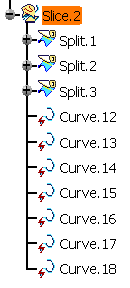
![]()