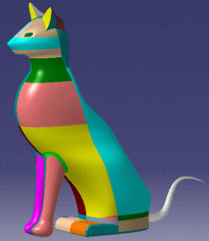
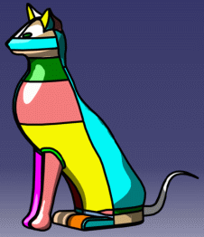
Creating a Cartoon Effect

This scenario explains how to generate a rendered image showing the drawing of contours around the geometry to create a cartoon-style effect.
 

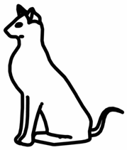
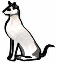
   Photorealistic image

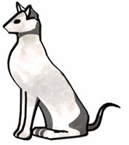
   Cartoon-style image

When applying a cartoon effect, it is recommended not to combine it with another lighting effect (such as glow, indirect illumination, etc.) since the aim is to produce a simplified rendered image.

Open the Cat.CATProduct document.
  1. Click Create Shooting to open the Shooting Definition dialog box then select the Effects tab: 

  2. Click Active to activate the cartoon effect.

  3. Select the desired cartoon effect, Contours only or Ink pen effect (you can use both effects, if desired):

    • Contours only
      Only the contours of the drawing are displayed on the rendered image.

    • Contour thickness
      Sets the thickness of the contour line to be applied when using Contours only or Ink pen effect. This value is expressed as a percentage of the overall image size.

      The preview displayed to the right is then automatically modified according to the thickness value you enter.
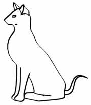
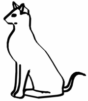
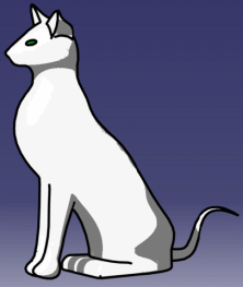
      Below are two examples for Contours only with two different thickness values:
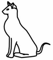
    Contours only "on"
    Contour thickness = 0.5
    Contours only "on"
    Contour thickness = 1
    • Ink pen effect
      Makes the thickness of the contour line depend on its orientation. The contour line is wider in the stroke direction.

      The preview displayed to the right is then automatically modified according to the thickness value you enter.
      Below are two examples for Ink pen effect with two different thickness values:
    Ink pen effect "on"
    Contour thickness = 0.5
    Ink pen effect "on"
    Contour thickness = 1
    Colors do not look the same when using cartoon effects. The reason is that only two colors are used for each applied material (one for shadowed areas and one for illuminated areas).
  4. Click OK to validate.

    You are now ready to render the shooting by clicking Render Shooting (you can also right-click the Shooting item in the specification tree then select Render Single Frame).

    The image is computed with a "complete" model, the contours are displayed during the post-processing phase only.

    Below are two examples using both Contours and Ink pen effect:

    Contour thickness = 0.5
    Ink pen effect "on"
    Contour thickness = 1
    Ink pen effect "on"
    Usually, a contour is drawn between two points of the image when the normal or depth difference between these two points is greater than a given threshold. In addition to that, a contour is also drawn if different materials (or graphic attributes) are applied.
    For instance, the cartoon rendering of the model below...
    ... gives this result if a different material has been applied onto each face: ... gives this result if the material has been applied directly onto the part:
    This enables to control the contour location using materials. In other words, if you want a contour to be drawn between two surfaces, you just need to apply a material onto each of these two surfaces. You can even apply the same material onto each surface because two materials applied onto two different supports are considered different for the rendering process (even if the same material has been applied as a linked material).
    Inversely, if you do not want any contour to be drawn between two surfaces, you have to apply a material onto their parent in the graph.