Open the
Rotate.CATPart document for Part Design workbench.
-
Click Rotate
 .
.
The application issues a question about the result you wish to obtain:- you can decide to keep the new specifications induced by the operation: in this case, just click Yes to go on using the command you have just selected.
OR
- you can decide not to keep the new specifications: in this case, click No to cancel the command you have just launched.

-
Click Yes.
The Rotate Definition dialog box appears.
The command applies to current bodies. Since PartBody is the current body, the command does not affect Pad.2.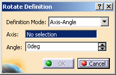
-
-
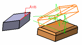
Axis-Angle (default mode): the rotation axis is defined by a linear element and the angle is defined by a value that can be modified in the dialog box or in the 3D geometry by using the manipulators.
-
Axis-Two Elements: the rotation axis is defined by a linear element and the angle is defined by two geometric elements (point, line or plane)
-
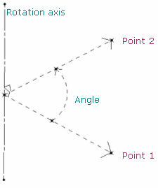
Axis/point/point: the angle between the vectors is defined by the selected points and their orthogonal projection onto the rotation axis.
-
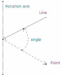
Axis/point/line: the angle between the vector is defined by the selected point and its orthogonal projection onto the rotation axis and the selected line.
-
Axis/line/line: the angle between the direction vectors of the projection is defined by the two selected lines in the plane normal to the rotation axis.
In case both lines are parallel to the rotation axis, the angle is defined by the intersection points of the plane normal to the rotation axis and these lines.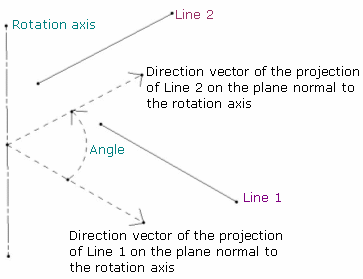
-
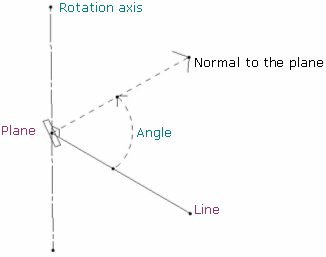
Axis/line/plane: the angle is defined between the selected line and the normal to the plane.
-
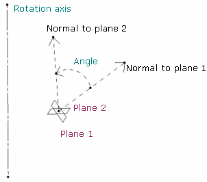
Axis/plane/plane: the angle is defined between the line normal to the two selected planes.
-
-
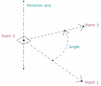
Three Points: the rotation is defined by three points.
-
The rotation axis is defined by the normal of the plane created by the three points passing through the second point.
-
The rotation angle is defined by the two vectors created by the three points (between vector Point2-Point1 and vector Point2-Point3):
-
The orientation of the elements (lines or planes) is visualized in the 3D geometry by a red arrow. You can click the arrow to invert the orientation and the angle is automatically recomputed. By default, the arrow is displayed in the direction normal to the feature (line or plane).
For instance, in the plane/plane mode, the arrow is displayed on each plane: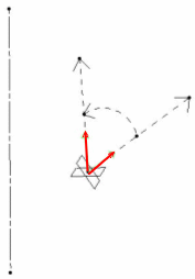
-
-
For the purpose of our scenario, set Three Points as the definition mode you want.
-
Select three vertices of Pad.2 as the three points required.
The application calculates the rotation axis from these points: altogether they create a plane. The normal to that plane passing thru the second vertex you selected is the rotation axis that will be used. The rotation angle is defined by the two vectors created by the three vertices (between vector Point2-Point1 and vector Point2-Point3):Example 1
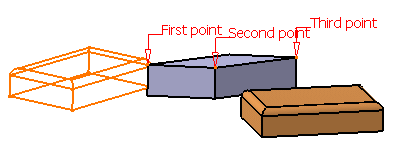
Example 2
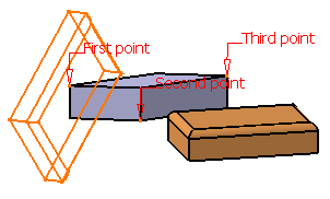
-
Click OK to create the rotated element.
The element (identified as Rotate.xxx) is added to the specification tree.