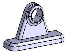
-
Click Remove Face
 .
.
The Remove Face Definition dialog box appears.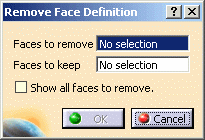
-
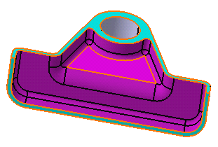
Select the inner face as the face to be removed.
The face turns purple indicating that it will be removed.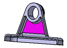
-
Click the Faces to keep field and select both faces as shown.
The faces turn blue, indicating that they will not be removed.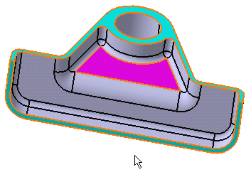
-
Check the Show all faces to remove option to preview all the faces adjacent to the purple face that will be removed.
-
Click OK to confirm.
All of the faces have been removed. The new feature identified as RemoveFace.XXX is added to the specification tree.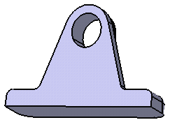
-
Launch the command again and select the faces as shown as the faces to be removed.

Two contextual commands are available from the Faces to remove field:
-
Click OK to confirm.
All selected faces have been removed. The new feature identified as RemoveFace.XXX is added to the specification tree.