We recommend you the use of this command to speed up your design.
-
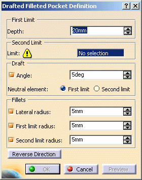
Select the profile to be extruded, that is Sketch.2.

-
Enter 22 as the pocket depth value.
-
Selecting a second limit is mandatory. Select Pad1 top face as the second limit.
Your specifications for creating the pocket are now defined. -
Let's go on with the draft definition. Enter 7 as the draft angle value.
Drafting faces is optional. If you do not wish to use this capability, just uncheck the Angle option. -
Check the Second limit option to define the neutral element. So, note that the pad top face is also used as the neutral element.
-
Enter 4 as the radius value to define the three fillets.
-
Lateral radius: defines the fillets on vertical edges
-
First limit radius: defines the round corner fillets
-
Second limit radius: defines the filets on the edges of the second limit.
Filleting edges is optional too. If you do not wish to use this capability, just uncheck the options.
-
-
Click Preview to check if the application can compute the fillets properly.
Clicking Preview previews the pocket, the draft and the fillets and display them in the specification tree. If you have deactivated the draft or fillet options, the draft or the fillets are then displayed as deactivated features in the tree, i.e. with red parentheses.
In the specification tree red parentheses appear on EdgeFillet.1, meaning that it cannot be computed by the application. Looking more closely at this fillet you can see that due to the shape of the initial sketch, it is effectively impossible to compute that fillet.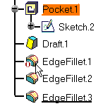
Note that there is a priority in the order of appearance of the fillets (from top to bottom) in the specification tree. The first fillet corresponds to the Lateral radius option in the dialog box, the second fillet to the First limit radius option and the last fillet to the Second limit radius option.
-
Click OK to create the features.
If you look at the specification tree, you will note that you have created:- one pocket
- one draft
- two fillets
This implies that if you want to edit the drafted filleted pocket, you need to double-click the appropriate feature. This is your new part:
