

![]()
|
|
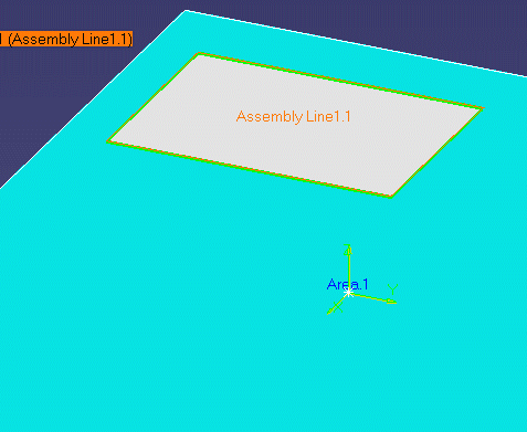
This task shows you how to create an area that has more than one contour. . . . . | |
|
|
There may be times when you need
to work with areas that are physically not contiguous, but which you want
to treat as a single area logically. An example may be two (or more) work
areas in a factory separated by a walkway. If you create an area with more
than one contour, all the different contours (or areas) you have created
will be treated as one logical area, even though they are physically
separated. This will, for instance, allow you to more easily analyze
available space for placing work cells. In the example below you have one
assembly line and you want to add a second contour to it.
|
|
|
|
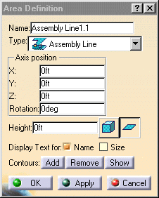
1. | Bring up the definition panel
(or dialog box) for the assembly line. (A) Click
Edit in the menu bar, (B) then on the line that
corresponds to the area for which you want a second contour, e.g. "assembly
line1.1 object" and (C) then on Definition.
This displays the Definition Panel. (You can also press
Ctrl+Enter to display the panel. Or
click the right mouse button and then follow from Step B above.)
|
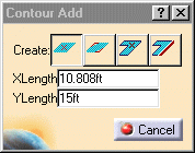
| 2. | Enter your information and click
Add. This brings up the Contour Add
dialog box. Displayed functions are similar to the Area Creation dialog
box, with the difference that the Rectangular - Corners
|
|
| 3. | Enter information and make your selections, then click the left mouse button to create the second contour and click OK. The second contour is created. | |
|
|
Since all contours you create for one area are considered part of that area, only one object will display in the specifications tree, in this case Assembly Line1. | |
|
|
||