Create the Assembly Template
-
Open the PktTowHook.CATProduct file.
-
From the Start > Mechanical Design menu, access the Drafting workbench. The New Drawing Creation Window is displayed.
-
Select the All views configuration and click OK.
-
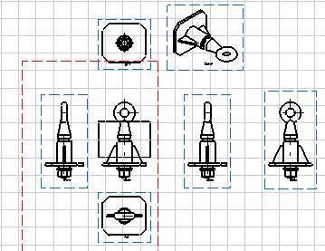
The drawing corresponding to the pad is generated.

-
Save your drawing and close the file. Click here to see the generated drawing.
|
 |
-
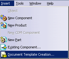
In the Document Template Definition window, define the document template.
|
|
|
|
|
|
|
|
|
|
|
|
|
|
|
-
Save your file and close it. Click here to open the result .CATProduct file.
Instantiate the Assembly Template
-
Open the PktDestinationProduct.CATProduct file.
-
From the Start > Knowledgeware menu, access the Product Knowledge Template workbench.
-
Click the Instantiate from Document icon (
 )
and select the
PktTowHook_result.CATProduct file in the File Selection
window. The Insert Object dialog box is displayed.
 -
Select the visible face of the pad. Face is displayed in the Insert Object dialog box.
-
Select the pocket in the Geometry.
-
Expand the Input_Cylinder node and select the Extract.1.
-
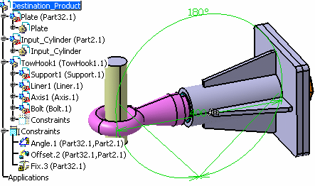
Click OK to validate. The assembly template is instantiated...

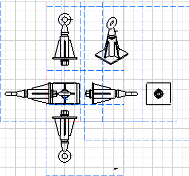
and the associated drawing is updated accordingly (click here to open the generated drawing).
 |
![]()