Declaring Input Data

This task explains how to declare data as to-be-entered by the user and how to fill in the dialog window which is displayed before the document is generated. Not all data can be declared as inputs. 

Data can be entered by the user provided they have been declared as Inputs by using the Input keyword in the script. When the script is generated, a dialog box is displayed the list of values to be entered to generate the document. See the Input Keyword for more information on this keyword.

  File Paths, Feature Names and Parameter Values

  1. In the Product Knowledge Template workbench, click the icon. The Knowledgeware Script Editor is displayed.

  2. Enter the script below 

    import Input : FilePath "Name of the CATPart to be imported";
    Pad1 isa CATPart
         {
           mypad isa Part
             {
               X = 10mm, Input : Length "Enter the pad length";  
               PartBody, Input:Name "New PartBody Name" isa BodyFeature  
                 {
                   S isa Sketch.1{}
                   P isa Pad("S"){}
                 }
              }
         }
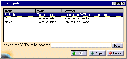
  3. Click Generate. The dialog box below is displayed:

  4. To enter the FilePath input, click Select then select the PktSketchToImport.CATPart sample. Click Apply.

  5. The X value is now highlighted in the dialog box and you are prompted to enter the X value, that is the pad length. To use the default value, click Apply. Otherwise, enter a new value in the X field, then click Apply.

  6. If need be, repeat this operation for the Name input. Click Apply to enter the Name value. OK must now be active. (OK is grayed out if there is still one or more inputs to be specified). Click OK. The extruded pad is generated.

Edges

  1. In the Product Knowledge Template workbench, click the icon. The Knowledgeware Script Editor is displayed.

  2. Enter the script below: 

    MyBox isa CATPart 
      { 
        BoxPart isa Part 
          { 
         PartBody isa BodyFeature 
           {
              Box1 isa Box 
              { 
                 Width = 20.0 mm ;
                 Height = 25.0 mm ; 
                 Length = 15.0 mm ;
               } 
            } 
         }
      } 
  3. Click Generate. A box is displayed in the geometry area.

  4. Back to the script editor. Add the statements related to the fillet and hole creations to your script:

    MyBox isa CATPart
     { 
      BoxPart isa Part 
       { 
        PartBody isa BodyFeature 
         {
          Box1 isa Box 
           { 
            Width = 20.0 mm ;
            Height = 25.0 mm ; 
            Length = 15.0 mm ;
           } 
           /* Added statements - Start */
           fillet2 isa ConstantEdgeFillet (//right-click, select the Get Edge command and click an edge in the Geometry)
                       {
                        Radius =2.0 mm;
                       }
           /* Added statements - End */
        } 
      }
     } 
  5. Click Generate. The fillet is created.

Features

  1. In the Product Knowledge Template workbench, click the icon. The Knowledgeware Script Editor is displayed.

  2. Use the File > Open command to open the PktInputFeature0.CATGscript macro which is delivered as a sample. Don't remove the comments corresponding to the line creation.

  3. Click Generate. The Po1 and Po2 points are created in the geometry area and the specification tree is updated accordingly.

  4. In the script editor, remove the comments to create L, then click Generate. The "Enter Inputs" dialog box is displayed. Only one input is to be entered by the end-user. Click Select, then select the Po1 feature in the specification tree.

  5. Click Apply then OK. The line joining Po1 and Po2 is created.