 |
This chapter deals with the rules the Generate Final
Holes and Pads tool must comply with. This tool allows you to:
- use a simplified representation
of holes/pads throughout the construction of your mold to improve performances,
- and replace this simplified representation by the actual holes/pads
when you are finished with the construction:
- select the required plates and launch the tool,
- the actual holes/pads are created and the simplified representations
are removed.
The Generate Final Holes and Pads
tool:
- is proposed for a CATPart or a CATProduct (the command takes all the
children CATParts of the CATProduct into account).
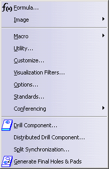
- is available through the Tools menu or the contextual menu
of the plates,
- applies to Assemble or Add/Remove operations on drilling bodies named
TapHole*, DrillHole*, Pocket*, Pad*
(those names are compulsory),
- is used at the end of the construction of the mold,
- cannot be undone (once the actual holes/pads are created, you
cannot revert to their simplified representation).
The simplified representation of holes and pads:
- is managed only by the Drill from/To/Between From and To
capability,
and not by the Drill Component and the Distributed Drill
Component tools,
- is ignored if it is empty or missing,
- appears in plates with the same visibility as they have in the
component,
- must be published to be taken into account,
- a drilling body is compulsory for each simplified representation of
holes and pads.
You must create this simplified representation:
- in a Geometrical Set in the CATPart of the component,
- the drilling bodies of the component must be named TapHole*or
DrillHole*or Pocket* or Pad* (those names
are compulsory),
- the name of Geometrical Set containing the definition of the
simplified representation is NameOfDrillingBody_S*,
e.g. the
Geometrical Set containing the simplified representation of DrillHole*
is named DrillHole_S*, that of Pocket1 is named
Pocket_S1.
- the simplified representation is defined by points, sketch, lines and
curves.
At least one of those elements must be present in the Geometrical
Set, otherwise the simplified representation is ignored.
The simplified representation will be used automatically whenever
applicable.
Its position is defined with respect to the component.
The component does
not know which plates are impacted, therefore the simplified representation
may appear distant from the plate it will drill.
If the simplified representation is useful to understand the design
quickly, it is useful to see the plates from the Z direction of the die or
to create very long lines in the direction of the component axis.
If this
visualization is not required, we recommend you create the simplified
representation in NoShow in the component.
Specific behavior:
- If the component is de-activated, the simplified representation is
also de-activated,
- Delete command: the simplified representation is deleted in
the corresponding plates,
- Replace/Add new instance/Add new reference/Isolate capabilities: the
behavior of the simplified representation is that of the standard holes,
- Edition: the simplified representation is managed as in creation.
|