Editing a tooling component will modify its impacts on its environment, as well as the impacts it receives from its environment. As a consequence it is easy to create complex relational design with the Mold Tooling commands. It is necessary to define the rules applicable to tooling components and tooling impacts in order to:
- maintain the integrity of the Die/Mold design,
- keep the relational design as transparent as possible for the user,
- promote design re-use,
- ensure an easy understanding of the Die/Mold after the tooling components have been inserted and their impacts performed,
Definitions
- Tooling Component Template:
- It is a tooling component not yet inserted in a Die/Mold, but which complies with the Mold Tooling Design rules, i.e. a component proposed in a manufacturer catalog or a component you have created in your own catalog.
- Tooling component:
- It is a tooling component inserted in a Die/Mold, via the Insert
component commands or the Add New Instance command. It can have one or
several instances.

When you insert a component in a Die/Mold, you actually copy the tooling component template from the catalog to the Die/Mold. As a consequence, if you modify the tooling component template in the catalog, the tooling component in the Die/Mold is not modified. - Tooling Sub-components:
- They are sub-products or sub-parts of a tooling component. It is recommended that they are tooling components themselves, but it is not mandatory.
- Shared sub-components:
- They are created with the option Several Instances per Reference.
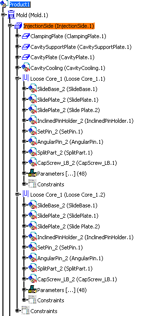
Example: We have created two instances of Loose Core_1, which share the same sub-components, e.g. SetPin_2. If we modify the geometry of SetPin_2 in Loose Core_1 (Loose Core_1.1), the geometry of SetPin_2 will also be modified in Loose Core_1 (Loose Core_1.2).

- Tooling Component Environment:
- It is the root product in which the tooling component is inserted, e.g. a Die or a Mold with all the already inserted components.
Tooling Impacts
The notion of impact of a tooling component is expressed from the point of view of the component itself:
- a tooling component can modify the geometry of the environment in which it is inserted. The mechanism which creates this modification is called an impact OUT.
- a tooling component geometry can be modified by the geometry of the environment in which it is inserted. The mechanism which creates this modification is called a impact IN.
Some Mold Tooling Design commands such as Split Component, Drill Component, Distributed Drill Component can create those impacts, which are named tooling impacts. Tooling impacts are both IN and OUT.
Context of Impacts
The minimal context of an impact is the smallest product in the structure
that contains both the impacted and the impacting components.
Example: if we consider Sleeve_Z022-2 inserted between the
ClampingPlate in the InjectionSide, the minimal context is
InjectionSide (that contains both the sleeve and ClampingPlate).

Tooling Part Interface
This is a mechanism created by the tooling command to report the IN and
OUT impacts from one context to another.
It takes the form of a CATPart, with a name beginning with TlgItf_.
Example: Sleeve_Z022_2 is inserted between the ClampingPlate in the InjectionSide and the SettingPlate in the EjectionSide. TlgItf_EjectionSide conveys the impact information from the InjectionSide to the EjectionSide.
Geometry of the Tooling Component
You can consider the following:
- the geometry of the component itself,
- the geometry used for the tooling impacts OUT (tooling component
output features):
- solids used for tooling drills,
- surfaces used for tooling splits,
- the geometry that is the input of tooling impacts IN (tooling
component input features):
- solids used for tooling drills,
- surfaces used for tooling splits,
- non tooling input (surfaces, wireframes, solids).
- Special case of the Tooling Component Dummy Input
- This is a virtual geometry in the Tooling Component Template, that creates an Impact IN for that component. It is replaced by an actual geometry at insertion.
Impact Children
An impact is an operation which
- uses geometry located in one component (Tooling or not),
- copies it (with link) inside another component (Tooling or not),
- and then uses it to create operations inside the receiving component, using the result of the copy.
From the point of view of the impact:
- the component in which the geometry to copy is found is called impacting component,
- the component in which it is copied is called receiving component or impacted component.
- The set of all children of the impact operation in the receiving component (excluding the copy itself) is called “impact children”.
|
|
|
Management of Impacts
Destruction of a Tooling Component with the Delete Component
- The Tooling Part Interfaces used for its impact IN are deleted if they are no longer needed
- The component is deleted (in the Assembly sense)
- On option: the impacts OUT and all their children are deleted (the Tooling Part Interface is now empty). This is optional because the impacts OUT may be reconnected to another component, under certain circumstances.
- The impact children may themselves be output features of the receiving component. If the impact children are deleted, all the impacts using them as input become non synchronized.
Creation or Replacement of a Tooling Component
A Tooling Component can be viewed as a loop in a chain of relational design. In particular its may have Impacts OUT or receive Impacts IN.
If a new Tooling Component is inserted in an environment, by analogy with another Tooling Component already inserted (called Model), or if it replaces an existing Tooling Component, it is important to decide if this Tooling Component will be part of a similar chain or not, using one of the three following methods:
- construction of the impacts,
- propagation, i.e. analysis of the existing impacts and recreation of similar impacts,
- reconnection, i.e. using the impacts of a given component for another component.
The following table summarizes the possibilities:
| Impact Management | Creation of a Component | Replacement of a Component |
| Impacts IN | Construction | Construction Reconnection |
| Impacts OUT | Construction Propagation |
Construction Propagation Reconnection |
Rules
Tooling Component Template Rules
- All the inputs for Tooling Impacts OUT must be published at the level
of the Root of the Template.
All output features of catalogs are published. - All the predefined dummy inputs of Impacts IN are gathered in a
specific geometrical set called Isolated external references.
They are ignored by the Mold Tooling Design if this is not the case. - It is necessary to avoid direct links between a Tooling Component
geometry and a Tooling Component output feature.
To ensure consistency, use parameters and relations.
A warning message is issued if such links are found. - It is necessary to ensure consistency between sub-components of a Tooling Component Template by using parameters at the Root Level.
- If the tooling Component is an Assembly, it is recommended to define its sub-components as Tooling Components, to fully benefit from the Mold Tooling Design mechanisms. However it is not mandatory for Data Upward Compatibility reasons.
Rules for management of Impactable components
If a component is modified in a way which depends on its 3D position in the environment, precautions must be taken so that the modification does not affect the other representations of this components, located in other 3D positions:
- If a Tooling Component receives an Impact IN, it must be mono-instance
- If a Tooling sub-component receives an Impact IN, it must not be a shared component.
- A component which has dummy inputs is necessarily mono-instance
- A Tooling Component which is part of the Mold Structure is necessarily
mono-instance.
Add new instance command is not available. - A Component receiving an impact is necessarily a CATPart (even a sub-component within a Tooling Component can receive an impact IN)
Sub-component Rules
- It is not allowed to edit the sub-components of the Tooling Component.
The only way to modify them is via the Tooling Component itself by changing the parameters. - A Tooling sub-component may not send directly an impact outside of the
Tooling Component it belongs to, after instantiation.
The impact must be created via the father Tooling Component. - A Tooling sub-component may not send directly an impact inside the
Tooling Component it belongs to, after instantiation.
The impact must be created before instantiation of the Tooling Component, in the Tooling Component Template.
Tooling Part Interface Rules
- The Tooling Part Interface is not editable.
- Impacts in the components of a block come from within the block or else affects one of the block parts interface.
Tooling Update Rules
To prevent complex update loops, a Tooling Component should not receive Impacts IN and send impacts OUT at the same time. However there are numerous situations, current in Die Design, which require breaking this simple rule. Therefore it is necessary to define more detailed recommendations:
- It is best to prevent the situations of Tooling Components Impacting and Impacted at the same time
- If a Tooling Components is Impacting and Impacted at the same time, it is necessary to maintain independence between input features and output features, from the update/synchronization point of view.
- A Tooling Component which is part of the Mold Structure may not Impact
other components, except for Coolant Channels.
It is not available for splits nor drillings.
Constraints
The constraints reconnection is ensured only when:
- Component product structure is the same.
- Instance names of products in the replacing component are the same.
- Constraints reference the same published elements
Example: Management of the Impact IN for the Replacing Component
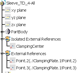
Replacing Component:

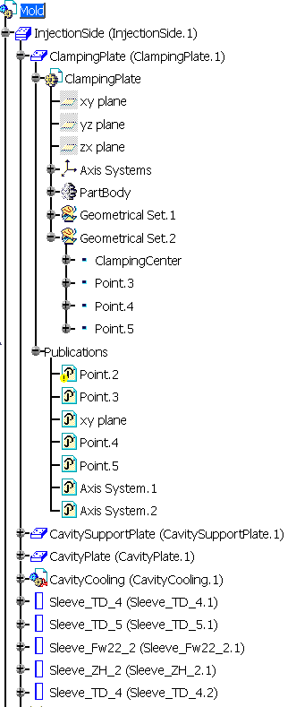
Mold:

You can see that the replacing component contains:
- an Isolated External Reference (Clamping Center). After the replacement, it will correspond to the Clanping Center of the ClampingPlate,
- two External References the definitions of those correspond to the publication paths of Point.2 and Point.3 of the ClampingPlate.
You can also note that the Publication Point.2 of the ClamplingPlate is broken (this is indicated by the yellow warning symbol).
We replace Sleeve_TD_4-All_1 in Mold by the replacing component using the
contextual menu item Replace Reference.
As we click OK to validate the replacement, the following dialog
box is displayed:

- The status of ClampingCenter is Isolated because it is an Isolated External Reference.
- Point.3 has been automatically reconnected to Point.3 (This is due to the publication of this point, used in the External Reference definition. As the point is a published element, the application can reconnect the external reference.)
- The status of Point.2 is Disconnected because its publication is broken.
When we select a line in the list, the buttons Isolate,
Delete and Reconnect become available. To isolate or delete
a component, simply click the corresponding button. To Reconnect a
component, click Reconnect and select a component in the specification tree.
Its name appears in the Reconnect with column. We have
reconnected the components as shown below:

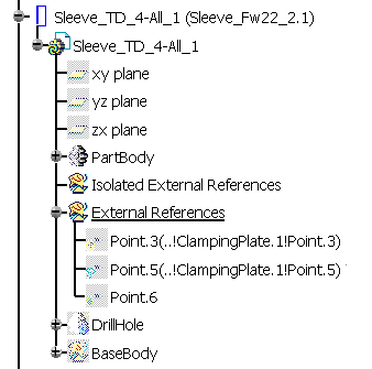
After validation, the structure of the replacing component in the mold
specification tree looks like this:
