-
Click the Create a new mold icon
 .
. -
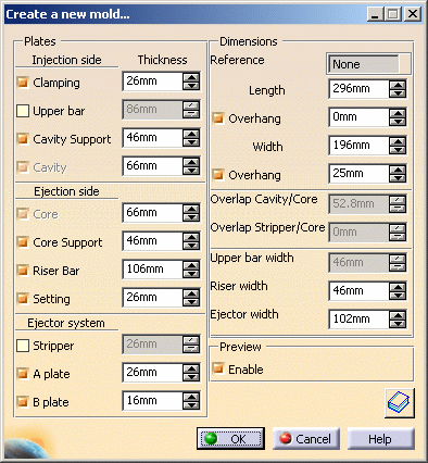
By default, the following dialog box is displayed.
Change the Dimensions, Length to 296 mm, Width to 196 mm and the Ejector width to 102 mm:
-
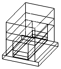
Hide the InjectionSide.
-
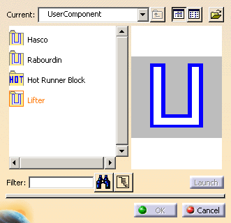
Click the Add User Component icon
 .
. -
Select the Lifter.
-
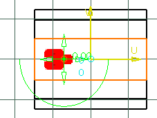
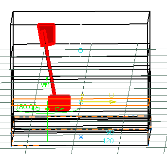
Pick EjectorPlateA.1. The sketcher is displayed. Pick a point near the undercut of your molded part. The loose core is visualized.
-
Select CorePlate as the Drill To element. Check that the loose core direction is correct or push the Reverse Direction.
-
You can use the manipulators to modify the position of the loose core.
-
You can tune up the parameters in the Parameters Tab according to your needs.
-
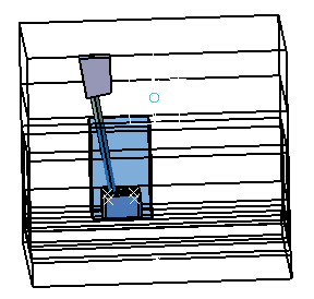
Click OK once you are satisfied with your settings. The loose core is created.
![]()