Work on blocks in a structure
In order to facilitate concurrent engineering, this application has been enriched with an automatic part interface to allow you to work on a single block (injection side, ejection side, ejector system, for example) even if components have been added to another block with results (drill holes, for example) that impact the block you are working on.
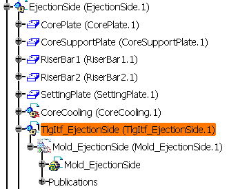
The part interface appears in the specifications tree when a block is impacted by the insertion of a component in another block and requires no user interaction whatsoever (it contains data on the context of contextual links) . Its name starts with Tlgitf but its end varies according to the block that is impacted. For instance, in the image below the part interface is called Tlgitf_EjectionSide because the ejection side is impacted by the insertion of a component in another block.
 |
Work on separate parts of blocks in a structure
When working in a concurrent engineering context on specific part of a block (a plate, for example), you can perform an analysis so as to know whether the part you are working on impacts another part of the mold or is impacted by another part of the mold. Analyzing a part of the structure produces a report informing you whether or not you can safely modify it.
-
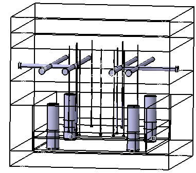
Open file CheckingClashAndClearance.CATProduct from the samples/CheckClash directory. Recall all of the parts that are hidden (the CorePlate , the InjectionSide and its components) via Hide/Show in their contextual menu.
-
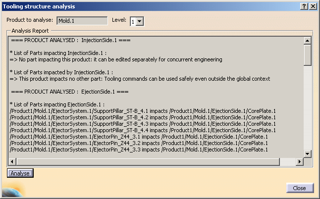
Choose Analyze/Tooling structure analysis... .
-
When the dialog box is displayed, click Mold1 in the tree, change the Level setting to 1 and click Analyze to generate the report.
-
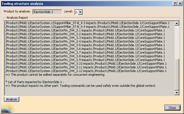
Now change the Product to analyze to EjectionSide.1, give a level of 0 and click Analyze to see the difference in results.
-
Click Close.
It is advisable to load the whole assembly (the whole mold) in order to obtain correct analysis results.
Defining what to analyze
Level and Product to analyze together define exactly what you analyze in the structure. Product to analyze gives the reference point and Level defines how far down into the structure you analyze with respect to that point.
For instance, when the Product to analyze is Mold.1, a Level of 0 will examine the mold with respect to any other Parts or Products in the viewer (the molded part, for example). If you change the Level to 1, the InjectionSide, the EjectionSide and the EjectorSystem will be analyzed. A Level of 2 will analyze the next level down, i.e. CorePlate , CavityPlate, etc.
![]()