- You can choose any component you wish to be drilled by any other.
- You can drill holes for a list of several drilling components in one shot.
- You can drill a newly added component (Component to Drill) by a previously existing Cooling System (Drilling Components).
-
Hide MoldedPart, EjectionSide and EjectorSystem
-
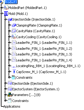
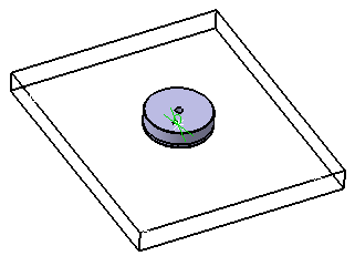
Expand the InjectionSide in the tree. Hide everything but LocatingRing_RB4_1 and ClampingPlate and recall CapScrew_M_1 from the NoShow to see its position.
-
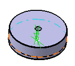
Hide the CapScrew. Note that there is no screw hole in the locating ring.
-
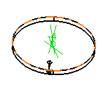
Now hide the locating ring. Note that there is a screw hole in the clamping plate.
-
Now re-display the locating ring and the cap screw.
-
Select Tools > Drill Component.
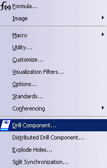
-
In the dialog box that is displayed, choose the locating ring as the Component to Drill and the cap screw as the drilling component.
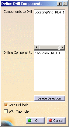
-
Click OK. A DrillHoleCapScrew_M_1.1 element has been added in the PartBody under LocatingRing_RB4_1.
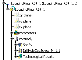
-
Hide the cap screw to see that the hole has been drilled.
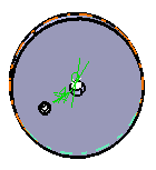
- You can enter a list of drilling components in the Drilling
Components field, by picking them either in the viewer or in the
specification tree:

-
Each element picked is taken into account once in the list. Picking one element twice does not remove it from the list.
-
You can edit this list:
-
Select one or several drilling component(s) and Click the Delete Selection button to remove this selection from the list.
-
You can now select another component to be added to the list.
-
Threads use the norm ISO 965-2. If you need to use a norm other than ISO 965-2, please refer to Reusing Values Already Defined in a File in Creating Threads and Taps in the Part Design User's Guide.
![]()