-
Select File > New
Select Part in the list. -
Using the contextual menu, edit the part properties,
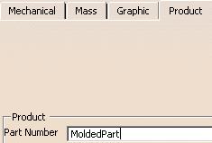
go to the Product tab and type MoldedPart as its Part Number.
(You can also begin by creating a mold base which automatically
contains
an empty MoldedPart where you can complete the steps given below). -
Open the Tel.CATPart file in the Samples directory. This opens a new viewer.
-
Select the PartBody in the specifications tree and copy it.
-
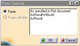
Select the Part in the MoldedPart viewer and use the Paste special function in the contextual menu.
-
Select AsResultWithLink in the dialog box and click OK.
This ensures that if the original part to mold is modified that the modifications will be applied to the MoldedPart.
-
You can now perform a scaling operation to take account of shrinkage:
- Select Start > Mechanical Design > Part Design.
- Right-click Body.2 in the specifications tree and select Define In Work Object in the contextual menu.
- Click Scaling
 .
. - Type a ratio value of 1.03 (for example), select the xy plane in
the tree as reference and click OK.
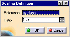
Repeat this action for the yz and zx planes with different ratio values.
-
Now determine the pulling direction with Draft Analysis or the Core and Cavity Design workbench:
the main pulling direction is defined when the CavitySurface and the CoreSurface are separated.
From the Core and Cavity Design workbench, you obtain surface joins for the CavitySurface and the CoreSurface.
An axis system is also created and used for the definition of the main pulling direction. -
Hide Core.1, Cavity.1, Other.1 and NoDraft_1deg.1.
-
Select Start > Shape > Generative Shape Design.
Insert an Geometrical set and name it PartingBody. -
Click Join
 .
. -
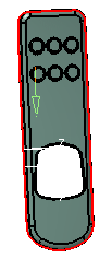
Select all of the bottom edges of the part. Click OK in the dialog box to confirm the action.
-
Right-click the new join in the specifications tree to open its properties and call it PartingLine.
-
Now you are going to fill the hole on the part to enable the split of the CavityPlate and of the CorePlate.
Join the curves around the hole and click OK in the dialog box.

-
Click Fill
 .
.
Select Join.2 in the specifications tree.
Click OK in the dialog box. The hole is filled.
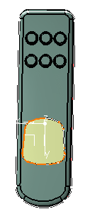
-
The next thing you are going to do is to create the parting surface.
- Click Sweep
 .
. - Click the Line Profile button in the dialog box.
- Select With reference surface for the Subtype.
- Select PartingLine in the specification tree for the guide curve.
- Select xy plane in the specification for the Reference surface.
- Type a value of 20 mm for Length 1.
- Click OK.
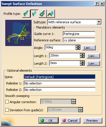
- Click Sweep
-
The parting surface is created
(if it is created in the wrong direction, i.e. in the inside of the part,
swap the values of Length 1 and Length 2).
Using the contextual menu, change the sweep name to PartingSurface.
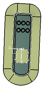
-
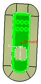
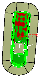
Click Extract
 .
.
Since the PartingSurface is shared by both the CavitySurface and the CoreSurface,
it is generated on both.
Select Tangent continuity in the Propagation type list and
pick any face on the upper surface in the viewer for the To Extract box.
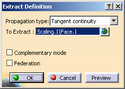
-
Turn the part over and repeat this step for the underside surface.
-
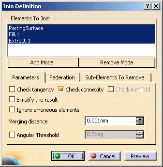
Click Join
 .
.
Select PartingSurface, the fill and the first extract in the specification tree.
Clear the Check connexity check box.
Click OK. -
Right-click the new join in the tree.
Select Properties in the contextual menu and change the name to CavitySurface. -
Repeat the action with the parting surface, fill and the second extract.
Call the new join CoreSurface.
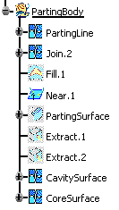
Your specification tree should look like this:
![]()