 |
This task shows you how to
create runners. |
 |
There are several restrictions concerning the manipulation
(notably when copying, pasting, deleting, dragging and dropping) of
components and drilled CATParts. Click here
for more information. |
 |
You must respect the following vocabulary:
- the imported part must be called MoldedPart,
- the Geometrical set containing the parting surface must be called
PartingBody,
|
 |
-
Open file
MoldWithMoldedPartAndComponents.CATProduct in the sample/MoldAndPart
directory.
Should some links of the CATProduct to the CATParts be
broken, please use the Desk command to restore them from the MoldAndPart
directory, or from the Split directory for GettingStarted01.CATPart.
-
Create the runner path in the sketcher, starting from, or
ending at, a projected gate point.
The sketch must be in a plane parallel to the xy plane of the
MoldedPart.
-
Click Add Runner
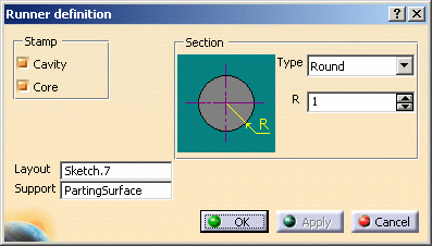
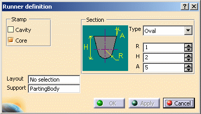
 . The Runner
definition dialog box is displayed. . The Runner
definition dialog box is displayed.

|
 |
PartingSurface is given as
Support in this case because a surface with this name was found
in the MoldedPart; if no surface with this name is found (No
selection) or if you want to create the runner path in another plane
you will have to choose one from the MoldedPart.
|
| |
-
Use Stamp to
create the runner either in the cavity and/or in the core.
-
Layout: select
the runner path on the screen. Its name is displayed in the dialog box.
-
Section:
select the section shape from the Type list: Round
or Oval. Then adjust the Height, Radius
and Draft angle values accordingly.
-
Click OK to create the runner and the gate
(until now it was only a point).
The runner and the gate pierce the CorePlate and/or the
CavityPlate.
The profile is automatically projected onto the SupportSurface.

|
 |
- The sketch elements must be continuous in tangency.
- You must project the gate point onto the sketch plane.
- In this release, only single-branch runners can be created.
|
 |
- Any components that are created after the runner and the gate
will not be pierced.
- If the type Oval is selected, you can define:
- the Radius,
- the Height,
- the Angle.
- The Angle value can be set to 0 degree, so that the oval section is an
exact U section.

|
|
Deleting a runner
|
|
If the runner was created in the core:
-
Edit the CorePlate:
use the contextual menu to delete the PartBody/Result of
MoldedPart_CoreRunnerBody,
-
then edit the MoldedPart:
- use the delete option in the CoreRunnerBody
contextual menu,
- put the BuildingBody into show mode,
- a projection of the sketch is created on the PartingSurface.
Use its contextual menu to delete it.
|
-
Perform the same actions in the cavity if that was where
the runner was created.
|
 |
If the runner was created in both the core and cavity, you must perform
the above actions in the core and the cavity. |
|
|
|
 |
![]()